110 Rockwell Automation Publication 1734-UM013N-EN-P - September 2017
Chapter 5 Configure the Module in a GuardLogix Controller System
b. Use the default values for Timeout Multiplier (2) and Network Delay
Multiplier (200).
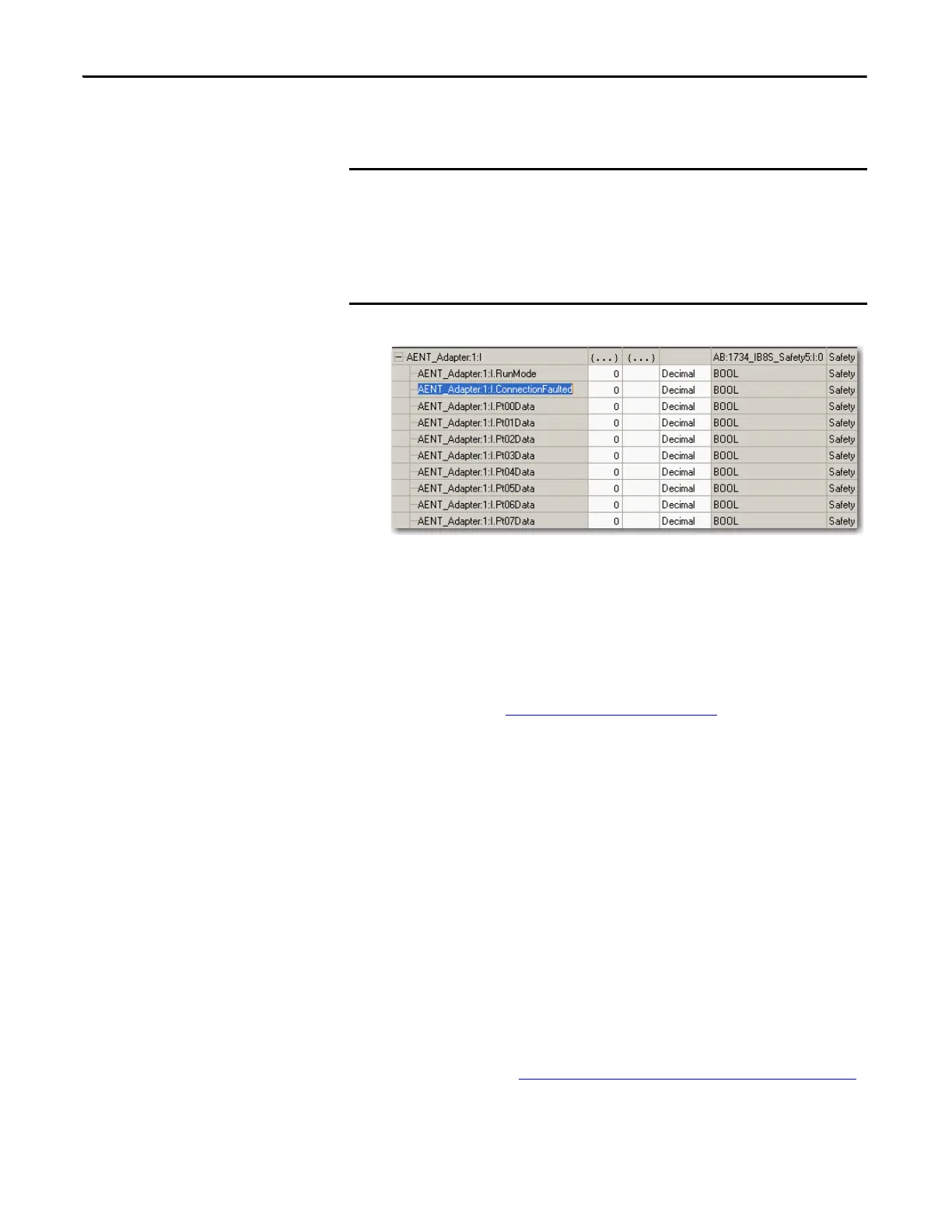
A connection status tag exists for every connection.
If the RPI and connection reaction time limit for the network are set
appropriately, then this status tag must always remain low. Monitor all
connection status bits to verify that they are not going high
intermittently due to timeouts.
For more information about the Advanced Connection Reaction Time
Limit Configuration dialog box, see the user manual for your
controller. See Additional Resources
on page 14.
Configuration Ownership
The connection between the owner and the POINT Guard I/O module is based
on the following:
• POINT Guard I/O module number
• POINT Guard I/O safety network number
• GuardLogix slot number
• GuardLogix safety network number
• Path from the GuardLogix controller to the POINT Guard I/O module
• Configuration signature
If any differences are detected, the connection between the GuardLogix
controller and the POINT Guard I/O module is lost, and the yellow yield icon
appears in the controller project tree.
For more information, see Replacing POINT Guard I/O Modules
on page 149.
To determine what is appropriate, analyze each safety channel. The default
Timeout Multiplier of 2 and Network Delay Multiplier of 200 creates a
worst-case input connection-reaction time limit of 4 times the RPI, and an
output connection-reaction time limit of 3 times the RPI. Changes to these
parameters must be approved only after a thorough review by a safety
administrator.
 Loading...


