48 Rockwell Automation Publication 1734-UM013N-EN-P - September 2017
Chapter 3 Guidelines for Placing Power Supplies and Modules in a System
Follow the safety precautions that are listed in Chapter 1 and the wiring
guidelines that are described in Chapter 4
before connecting a power supply to
the system.
To choose which types of power supplies meet your requirements, you must
consider the power consumption requirements for the 5V and 24V bus when
designing a POINTBus backplane.
Choose from these power supplies for the POINTBus backplane and field
power:
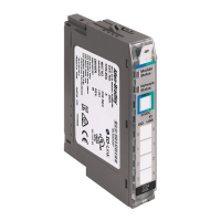
• Use the 1734-EP24DC expansion power supply to provide an additional
10 A of 24V DC field power and provide an additional 1.3 A of 5V current
to the I/O modules to the right of the power supply.
• Use the 1734-FPD field power distributor to provide an additional 10 A of
24V DC field power, and to pass through all POINT I/O backplane
signals including the 5V bus supplied to the left, without providing
additional POINTBus backplane power. This action lets you isolate field
power segments.
• Use the 1734-EPAC expansion power supply (for standard I/O modules)
to provide an additional 10 A of 120/240V AC field power and provide an
additional 1.3 A of 5V current to the I/O modules to the right of the
power supply.
See the POINT I/O Selection Guide, publication 17
34-SG001, for more
information on compatible power supplies.
If you use the 1734-EPAC expansion power supply to the left of the POINT
Guard I/O™ modules, you must use a 1734-FPD field power distributor or
1734-EP24DC expansion power supply. These distributors are used to isolate
POINT Guard I/O field power from the AC field supply.
5V POINTBus power is required to establish and maintain communication
(connection) between the module and the controller.

 Loading...


