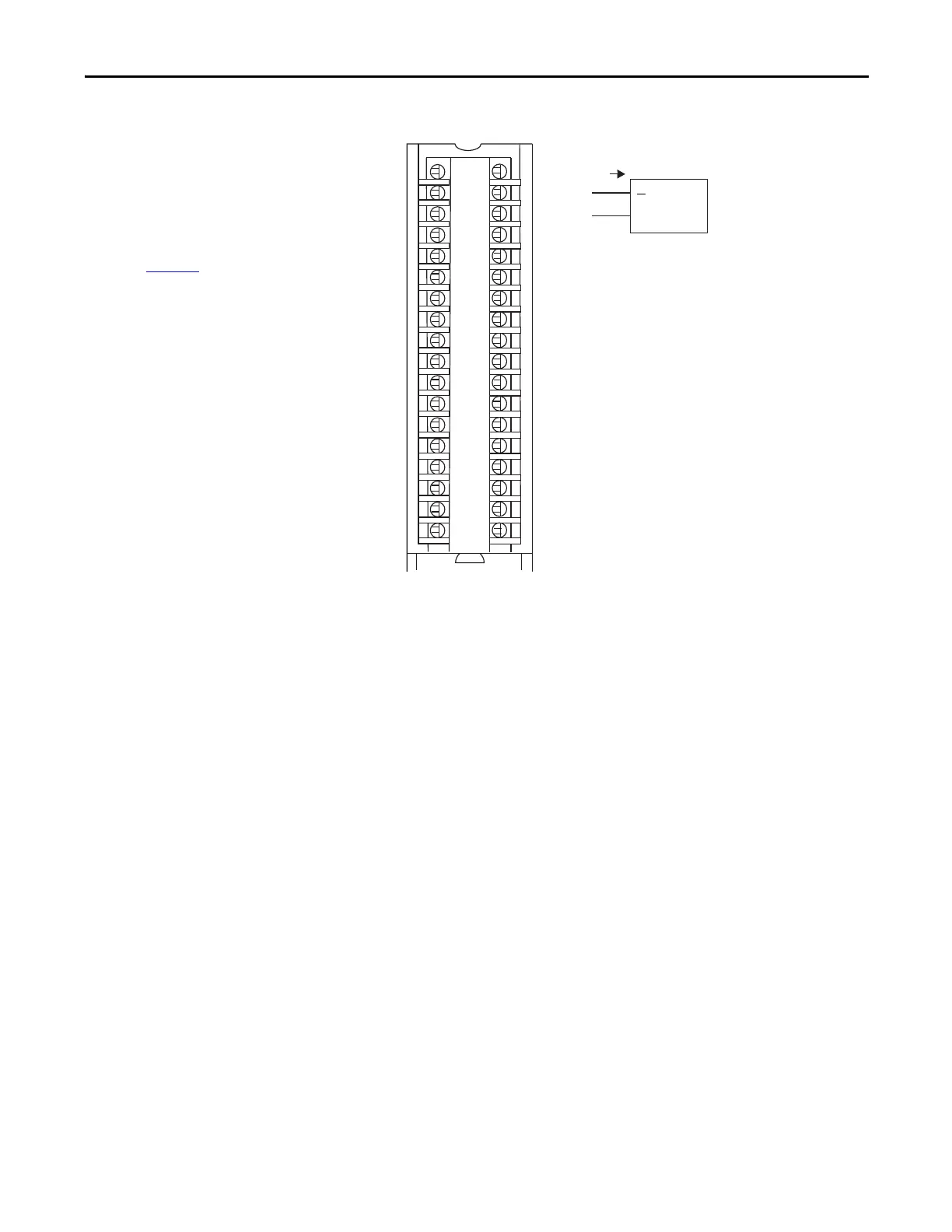
OUT_0/V
OUT_0/I
RTN_0
Not used
OUT_2/V
OUT_2/I
RTN_2
Not used
< 1000 User
Analog Output
Device
OUT_4/V
OUT_4/I
RTN_4
Not used
OUT_6/V
OUT_6/I
RTN_6
Not used
Not used
Not used
OUT_1/V
OUT_1/I
RTN_1
Not used
OUT_3/V
OUT_3/I
RTN_3
Not used
OUT_5/V
OUT_5/I
RTN_5
Not used
OUT_7/V
OUT_7/I
RTN_7
Not used
Not used
Not used
IMPORTANT: Remember the following:
• If separate power sources are used, do
not exceed the specific isolation
voltage. For more information on
module specifications, see the 1756
ControlLogix I/O Specifications
Technical Data, publication
1756-TD002
.
• Place additional devices anywhere in
the loop.
 Loading...


