1756 EtherNet/IP Communication Module 3
Rockwell Automation Publication 1756-IN050C-EN-P - December 2018
Install the Module
You can install or remove a module while chassis power is applied.
For equipment with multi-point network communication connections.
Follow these steps to install the module.
1. Set the network IP address on a module.
For more information about how to configure an EtherNet/IP network, see the EtherNet/IP Network Configuration User
Manual, publication ENET-UM001
.
Depending on the 1756 EtherNet/IP communication module, you can use some or all of these tools to set the network
Internet Protocol (IP) address:
• Rotary switches
• Bootstrap Protocol (BOOTP)/Dynamic Host Configuration Protocol (DHCP) server
• RSLinx® Classic software
• The Studio 5000® environment
The module uses these tools sequentially to set the IP address.
2. Determine module slot location.
3. Install the module.
a. Align the circuit board with top and bottom guides in the chassis.
b. Slide the module into the chassis.
Make sure that the module backplane connector properly connects to the chassis backplane. The module is properly
installed when it is flush with the power supply or other installed modules.
4. Connect the module to an EtherNet/IP network via an RJ45 connection.
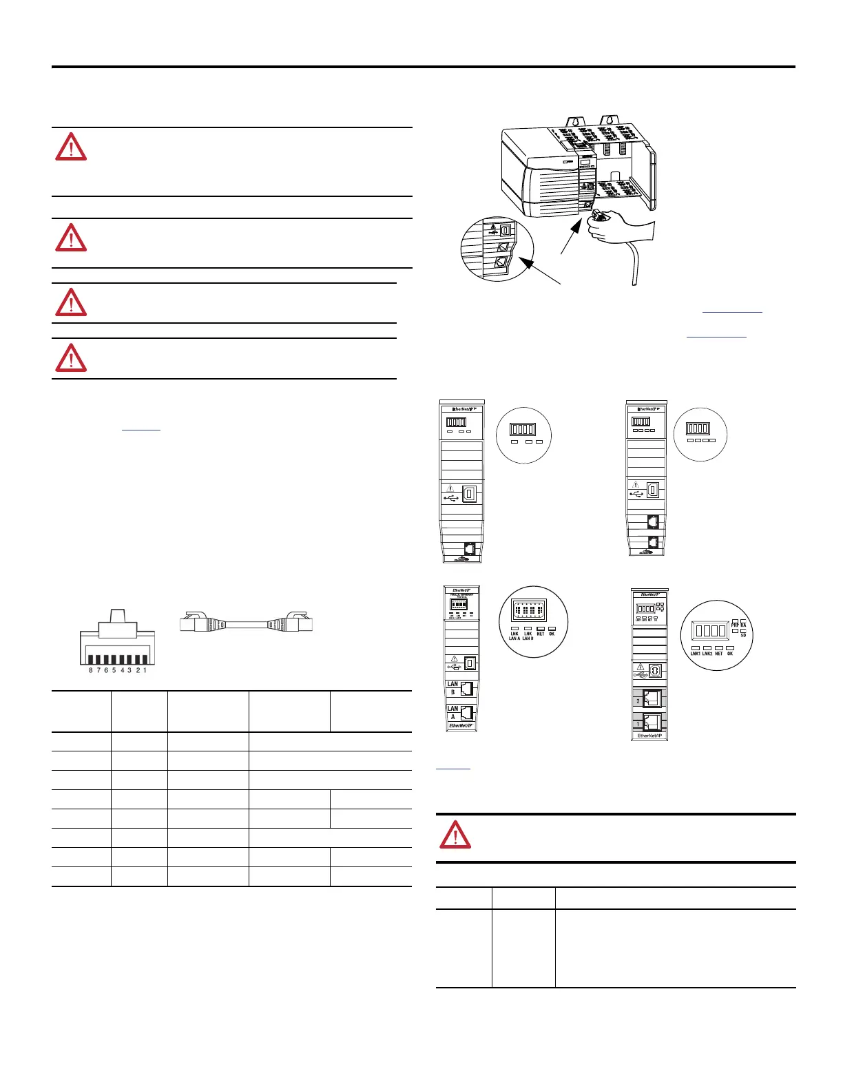
5. Attach the cable with the RJ45 connector to the Ethernet port on the module as shown.
6. Download the Add-on Profile from the Product Compatibility and Download website at http://www.ab.com
.
7. Connect to the module via the USB port (if the module is equipped with a USB port).
8. Download the firmware from the Product Compatibility and Download website at http://www.ab.com
.
9. Apply chassis power and check status indicators.
Status Indicators
These 1756 EtherNet/IP communication modules use the same status indicators. This graphic shows the front of the
module for these modules (Extended-temperature modules not shown.)
For more information on the status indicators, see the EtherNet/IP Modules Installation Instructions, publication
ENET-IN002
.
Network Connectors and Cable
This product includes a USB port.
WARNING: When you insert or remove the module while backplane power is on, an electric arc can occur.
The insertion or removal of the module while the backplane power is on can cause an explosion in
hazardous location installations.
Be sure that power is removed or the area is nonhazardous before proceeding. Repeated electric arcs can
cause excessive wear to contacts on both the module and its mating connector. Worn contacts can create
electrical resistance that can affect module operation.
WARNING: If you connect or disconnect the communication cable with power that is applied to this module
or any device on the network, an electric arc can occur. This connection or disconnection of the module with
applied power can cause an explosion in hazardous location installations.
Be sure that power is removed or the area is nonhazardous before proceeding.
ATTENTION: If you are using the 1756-EN4TR or 1756-EN4TRK above 50 °C(122 °F), it must be
installed in a Series C chassis.
ATTENTION: In order to operate over its full rated temperature range, the 1756-EN4TRXT must be
used with a Series C XT Chassis.
Connector
Number
Color
1585J 8-pin Cables
with Support for
10/100/1000 Mbps
1585J 8-pin Cables
with Support for
10/100 Mbps
1585J 4-pin Cables
with Support for
10/100 Mbps
1 White/Orange BI_DA+ TxData +
2OrangeBI_DA- TxData -
3 White/Green BI_DB+ Recv Data +
4BlueBI_DC+ Unused N/A
5 White/Blue BI_DC- Unused N/A
6GreenBI_DB- Recv Data -
7White/BrownBI_DD+Unused N/A
8BrownBI_DD- Unused N/A
WARNING: The USB ports are intended only for temporary use and must not be connected or
disconnected unless the area is nonhazardous. Do not use the USB port in hazardous locations.
The USB cable is not to exceed 3.0 m (9.84 ft) and must not contain hubs.
Modules Ports Requirements
EtherNet/IP Copper Ethernet Connector/cable: RJ45 connector according to IEC 60603-7, 2 or 4 pair Category
5e minimum cable according to TIA 568-B.1 or Category 5 cable according to
ISO/IEC 11801-3.
Connector/cable: For 1756-EN4TR, 1756-EN4TRK, and 1756-EN4TRXT, RJ45
connector according to IEC 60603-7, 4 pair Category 5e minimum cable
according to TIA 568-B.1 or Category 5 cable according to ISO/IEC 11801-3.
32457
Dual-port module
Single-port module
LNK1LNK1 LNK2LNK2 NETNET OKOK
LNK1LNK1
1
2
LNK2LNK2 NETNET OKOK
3245332453
LINKLINK
LINKLINK NETNET OKOK
3245232452
NETNET
OKOK
1
Single-port
module
Dual-port
module
32730
Parallel Redundancy
Protocol
Dual-port module
1756 -EN4TR
Dual-port module

 Loading...


