Rockwell Automation Publication IASIMP-QS024C-EN-P - August 2014 23
Prepare the CompactLogix 5370 L1 Controller Hardware Chapter 1
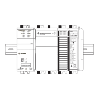
Wire Power to the Controller
This quick start uses a 1606-XLE120E NEC Class 2, switched-mode power supply to power the CompactLogix 5370 L1
controller. The controller used in this quick start is a CompactLogix 5370 L1 series B controller. Further wiring
information for the CompactLogix 5370 L1 series A controller can be found in the CompactLogix 5370 Controllers User
Manual, publication 1769-UM021
.
1. Verify that input power to the external power supply is turned off.
2. Mount the power supply on the DIN rail.
3. Wire input power to the power supply by
using the following terminals:
• (ground)
•L2 (neutral)
•L1 (line)
4. Connect a wire to the 24V DC+ terminal
on the top of the power supply.
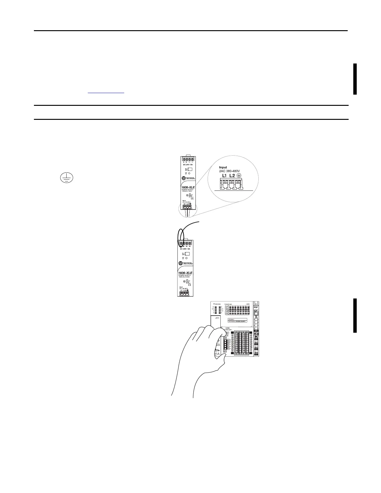
5. Loosen the screws securing the removable
connector to the CompactLogix 5370 L1
controller and pull the connector off of the
controller.
This section describes how to wire power to the controller. The controller is grounded by its connection to the DIN rail.
 Loading...