24 Rockwell Automation Publication IASIMP-QS023B-EN-P - December 2012
Chapter 1 Prepare the CompactLogix 5370 L3 Controller Hardware
5. Move the power supply’s bus level fully to the left until it locks.
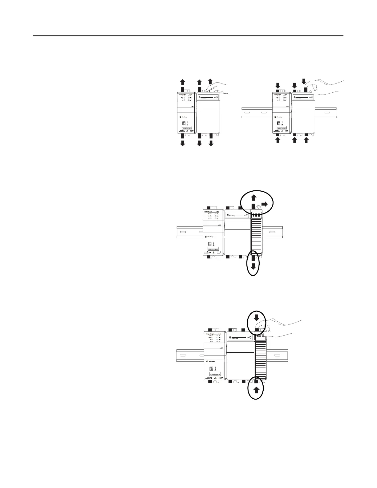
6. Mount the CompactLogix 5370
L3 controller and power supply on
the DIN rail.
a. Pull locking tabs out
b. Slide controller and power
supply into position.
c. Push the locking tabs in.
7. Mount the 1769-OB16 output module.
a. Make sure the output module’s
locking tabs are pulled out and
the module’s bus lever is in the
unlocked position, that is,
leaning to the right..
b. Use the upper and lower
tongue-and-groove slots to
secure the output module and
power supply together.
c. Move the output module back along the tongue-and-groove slots until the bus
connectors line up with each other.
d. Move the output module’s bus
lever fully to the left until it
locks.
e. Push the locking tabs in.
 Loading...

