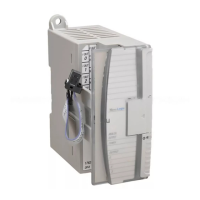
Communication Interface Module
Cat. No. 1784KT/B
Installation Data
10
ATTENTION: To avoid personal injury, always disconnect the
ac power before making the cable connection.
Connecting
Y
our 1784KT to a PLC2
To connect the 1784-KT to a PLC-2, follow the steps below:
1. Plug the 62-pin connector end of the 1784-CP2 cable into the
1784-KT and secure with captive screws.
1784 - KT
Board
Program
Panel"
1784 - CP2 Cable
16687a
2. Connect the opposite end of the 1784-CP2 cable into the PROGRAM
PANEL connector on the PLC-2.
3. Reinstall the ac power cord and turn on the computer.
Figure 1 shows cable pinouts for the 1784-CP2 cable.
Figure 1
Cable
Pinouts for the 1784CP2 Cable
4
5
6
48
7
27
26
1
2
3
4
7
8
A2 TXD
A2 TXD RET
A2 OUT0 RET
A2 OUT0
A2 RXD RET
A2 IN0 DET
A2 RXD
47
6
5
A2 IN0
Cable shield
tied to chassis
62 pin
D - shell
16688
To
Program Panel"

 Loading...


