FLEX I/O Isolated Output HART Analog Module 11
Publication 1794-IN120D-EN-P - September 2015
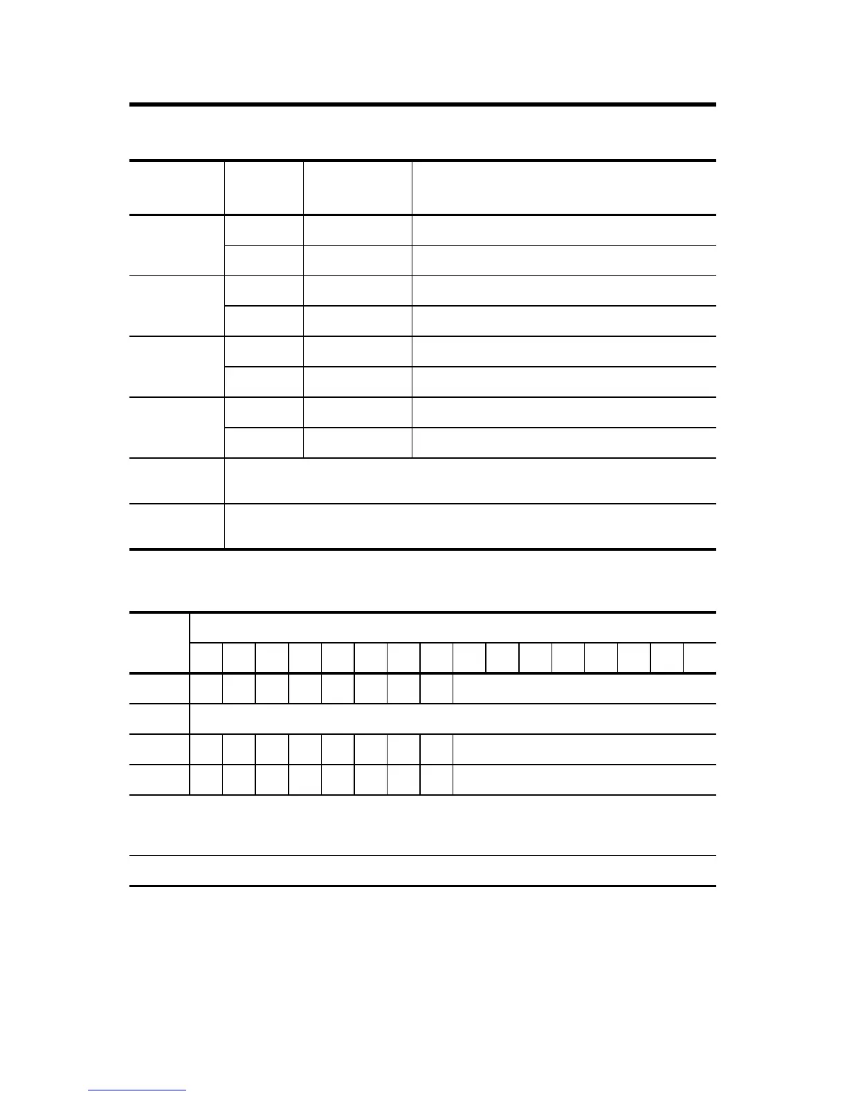
Input Map
4 Current O4 A-8
Current O4 Ret A-9
5 Current O5 A-10
Current O5 Ret A-11
6 Current O6 A-12
Current O6 Ret A-13
7 Current O7 A-14
Current O7 Ret A-15
-V DC
common
For catalog numbers 1794-TB3 and 1794-TB3S, terminals B-16…33 are internally
connected in the terminal base unit.
+V DC power For catalog numbers 1794-TB3 and 1794-TB3S, terminals C-34…51 are internally
connected in the terminal base unit.
Word Bit
1514131211109876543210
0 F7F6F5F4F3F2F1F0Diagnostic Status
1 Reserved
2 C7C6C5C4C3C2C1C0Reserved
3 X7X6X5X4X3X2X1X0Reserved
Fn =
Cn =
Xn =
Channel n Wire Fault Alarm for open or short circuit
(1)
Channel n HART Current Fault
HART Device Transmitter present
(1)
This alarm is disabled in Analog 0…20 mA formats (Formats 0, 1, 3) or if “Wire Fault Detection” is not enabled in
configuration.
0 = False; 1 = True
0 = False; 1 = True
0 = False; 1 = True
Note: Reserved data may not be shown in certain controller software
Wire Connections
Channel Signal
Type
Label
Markings
Catalog Numbers
1794-TB3 or 1794-TB3S Terminal
 Loading...


