5
6
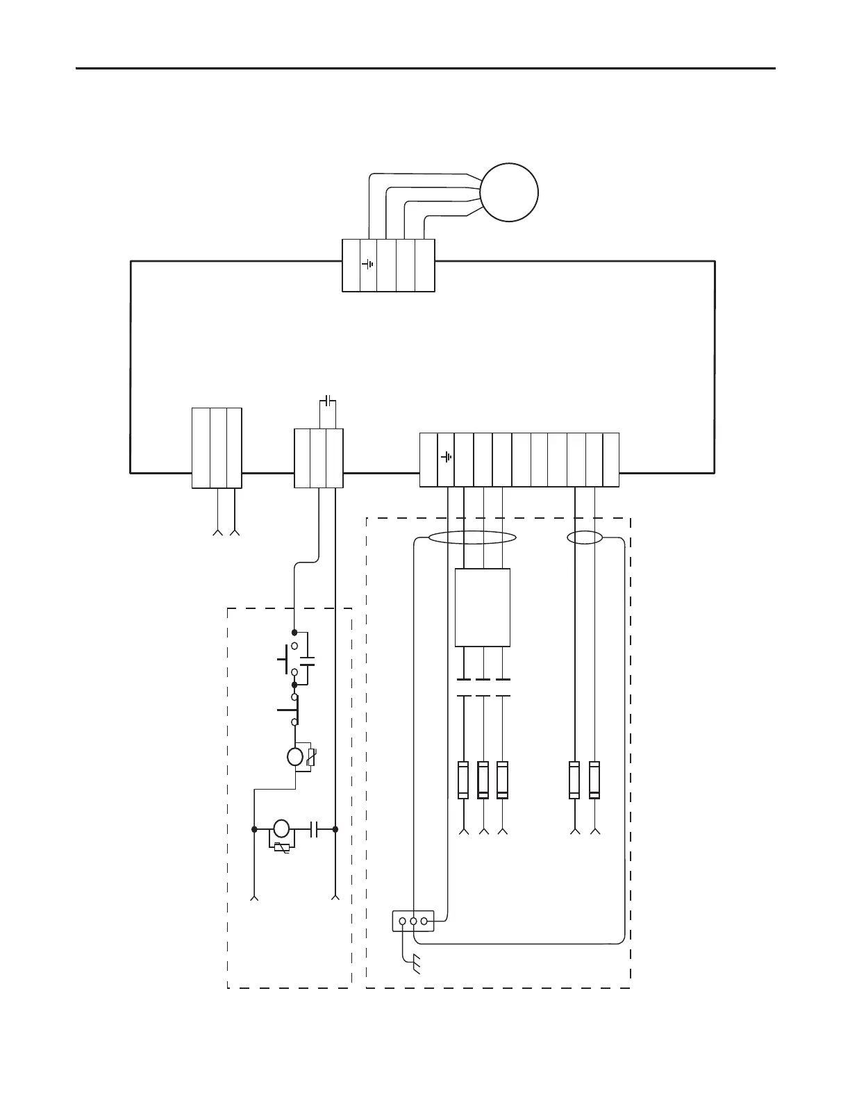
24V DC (Can also use
120/240V AC - see
“General Purpose Relay
(GPR Connector)” on
page 61 for ratings.
Connected components
must match input
power rating)*
M1* CR1*
STOP*
START
(Drive Main
Power On)*
GPR2+
GPR2-
GPR
CP_24VDC
CP_COM
CP
1
2
PE
U
V
W
T1
T2
T3
MP
R
S
T
DC+
DC-
0V AC
120 V AC
240 V AC
TB
PE
L1
L2
L3
CR1*
CR1*
Input Fusing *
See Note 2
Motor
Power
Cables*
* Indicates User Supplied Component
360° Shielding of Power Wiring
Required to Comply with EMC Requirements
Bonded Cabinet
Ground Bus *
Three Phase
Motor Power
Connections
* Indicates User Supplied Component
Three-phase
AC Input and
DC Bus Output
Connections
Single-phase
Fan Power
Connections
See Note 9
Additional connections required,
but not shown in this diagram:
1. Motor Brake (if used) and Feedback
2. Machine Feedback and Drive I/O
3. Drive Communications
Control
Stop String
See Note 8
Control Power
DC Input
Connections
+24V DC
Control Power *
See Note 7
Three-phase Input
(+10/-15%)
460VAC RMS,
50/60 Hz
See Note 1
Single-phase Input
(+10/-15%)
120V or 240 VAC RMS,
50/60 Hz
(120V AC wiring shown)
Three-Phase Contactor *
(M1 in Control String)
Three-phase
AC Line Filter *
See Note 3
Kinetix 7000 Drive
2099-BMxx-S
Motor*
Note 4
 Loading...


