80 Rockwell Automation Publication 2099-UM001D-EN-P - December 2012
Chapter 4 Connect the Kinetix 7000 Drive System
Removing the Ground Wires on 2099-BM09-S and 2099-BM10-S
Drives
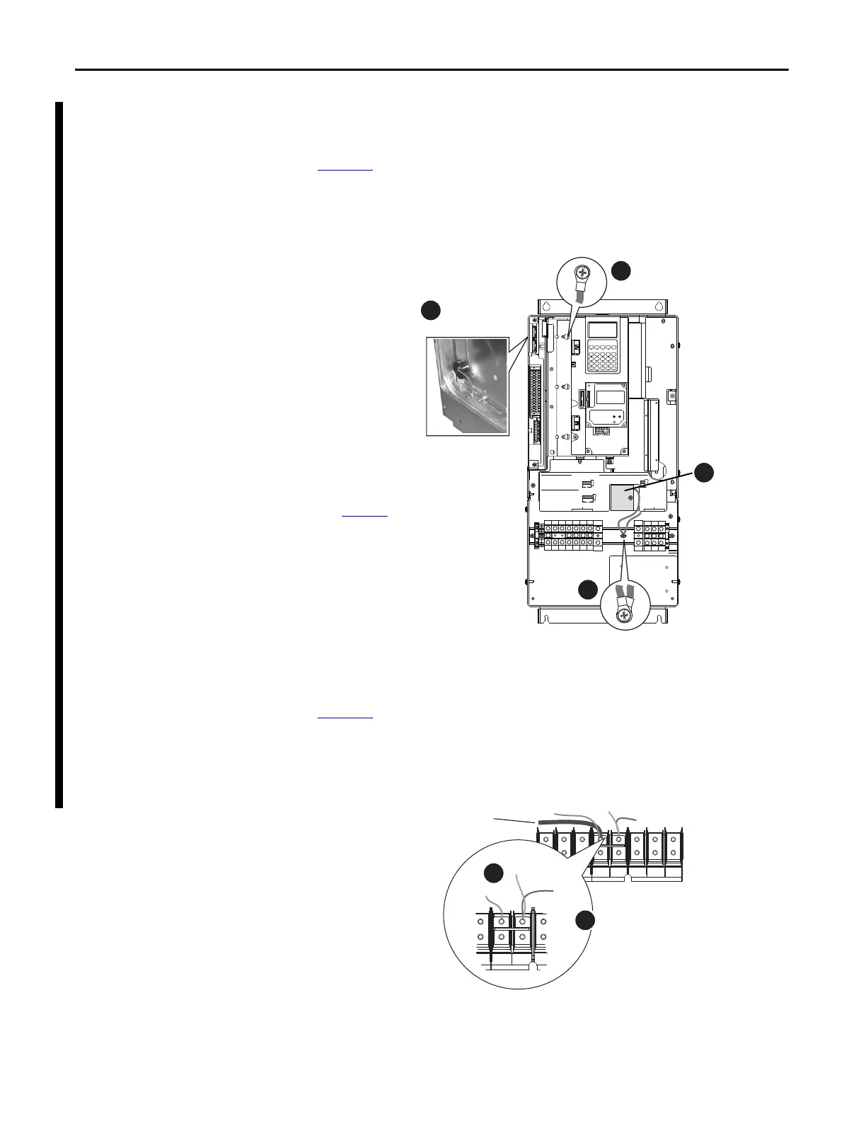
Figure 48 shows the locations of the common mode capacitor and MOV/input
filter capacitor ground wires in 2099-BM09-S and 2099-BM10-S drives. The
common mode capacitor ground wire is indicated by callout 3 and the MOV/
input filter cap ground wire is indicated by callout 4.
Figure 48 - Ground Wire Locations on Terminal Block of 2099-BM09-S and 2099-BM10-S
Removing the Ground Wires on 2099-BM11-S and 2099-BM12-S
Drives
Figure 49 shows the locations of the common mode capacitor and MOV ground
wires in 2099-BM11-S and 2099-BM12-S drives. The common mode capacitor
ground wire is indicated by callout 5 and the MOV ground wire is indicated by
callout 6.
Figure 49 - Ground Wire Location on Power Terminal Block of 2099-BM11-S and 2099-BM12-S
WIRE RANGE: 14-1/0 AWG (2.5-35 MM
2
)
TORQUE: 32 IN-LB (3.6 N-M)
STRIP LENGTH: 0.67 IN (17 MM)
USE 75 C CU WIRE ONLY
POWER TERMINAL RATINGS
WIRE RANGE: 6-1/0 AWG (16-35 MM
2
)
TORQUE: 44 IN-LB (5 N-M)
STRIP LENGTH: 0.83 IN (21 MM)
GROUND TERMINAL RATINGS (PE)
300 VDC EXT PWR SPLY TERM (PS+, PS-)
WIRE RANGE: 22-10 AWG (0.5-4 MM
2
)
TORQUE: 5.3 IN-LB (0.6 N-M)
STRIP LENGTH: 0.35 IN (9 MM)
17
21
INPUT ACOUTPUT
Optional
Communications
Module
9
Note: You must remove the DC-DC
converter and drive top cover to access
and remove the common mode
capacitor ground wire. See the Kinetix
7000 DC-DCConverter and ControlBoard
Kits Installation instructions, publication
2099-IN002
, for instructions.
3
4
4
U
T1
V
T2
W
T3
R
L1
S
L2
INPUTOUTPUT
T
L3
PE PE
PE PE
MOV
CM Cap

 Loading...


