Rockwell Automation Publication IASIMP-QS024C-EN-P - August 2014 25
Prepare the CompactLogix 5370 L1 Controller Hardware Chapter 1
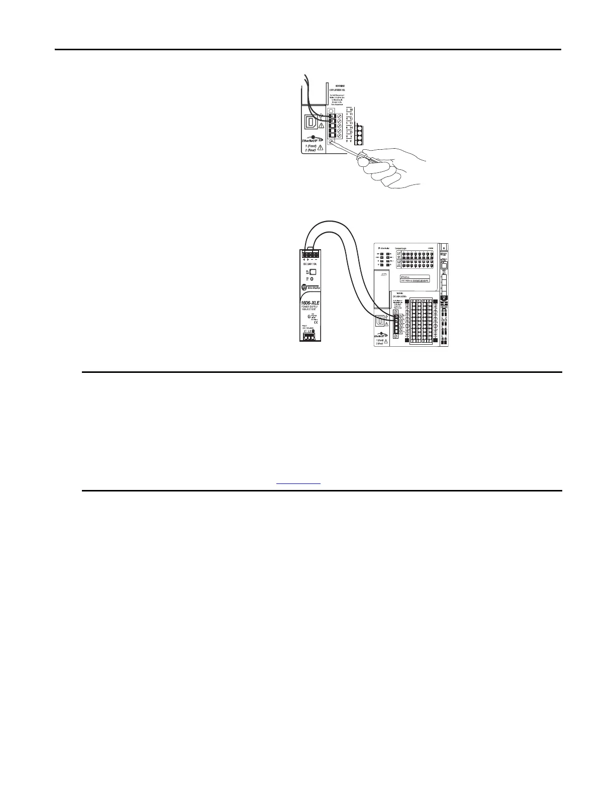
11. Secure the removable connector in place.
This graphic shows the 1606-XLP50E
switched-mode power supply that is
connected to the CompactLogix 5370 L1
controller.
12. Turn on incoming power to the external
power supply.
You wire only the VDC+ and VDC- terminals on the CompactLogix 5370 L1 controller’s embedded power supply to
complete the tasks in this quick start.
In real-world applications, you can have additional considerations that are related to connected power in an application,
such as connecting power to multiple controllers or connecting power to input and output devices that are connected to
the controller’s embedded I/O modules and local expansion modules via the FP+, and FP- terminals on the removable
terminal.
For more information on connecting power to the CompactLogix 5370 L1 control system, see the CompactLogix 5370
Controllers User Manual, publication 1769-UM021
.

 Loading...


