62 Rockwell Automation Publication IASIMP-QS024C-EN-P - August 2014
Appendix A Understanding Other Application Options
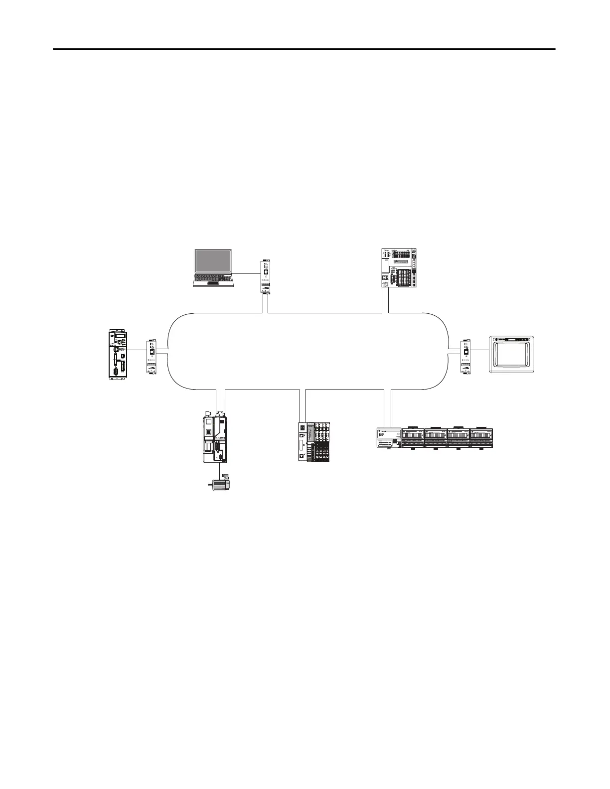
DLR Network Topology
A DLR network topology is a single-fault-tolerant ring network in which DLR-capable Rockwell Automation devices use
embedded technology and dual EtherNet/IP ports to establish a network that is resilient to single points of failure, recovers
faster when single faults occur, and does not require switches.
Configuring a DLR network topology requires you to complete a few tasks that do not apply to using a CompactLogix
5370 L1 controller in a linear or star network topology. For example, a DLR network topology requires that one
supervisor-capable network device be configured as the active ring supervisor. CompactLogix 5370 L1 controllers are
supervisor-capable devices on a DLR network.
This graphic shows a DLR network topology with a CompactLogix 5370 L1 controller.
02
0
1734-AENTR
Module
Status
Network
Activity
Network
Status
Point Bus
Status
System
Power
Field
Power
POINT I O
Link 1
Activity/
Status
Link 2
Activity/
Status
IP ADDRESS
Kinetix 6500
CompactLogix 5370 L1
1794-AENTR FLEX
™
I/O
•PanelView Plus
• 1783-ETAP
1783-ETAP
1734-AENTR POINT I/O
• Kinetix 350
• 1783-ETAP

 Loading...


