Rockwell Automation Publication IASIMP-QS024C-EN-P - August 2014 27
Prepare the CompactLogix 5370 L1 Controller Hardware Chapter 1
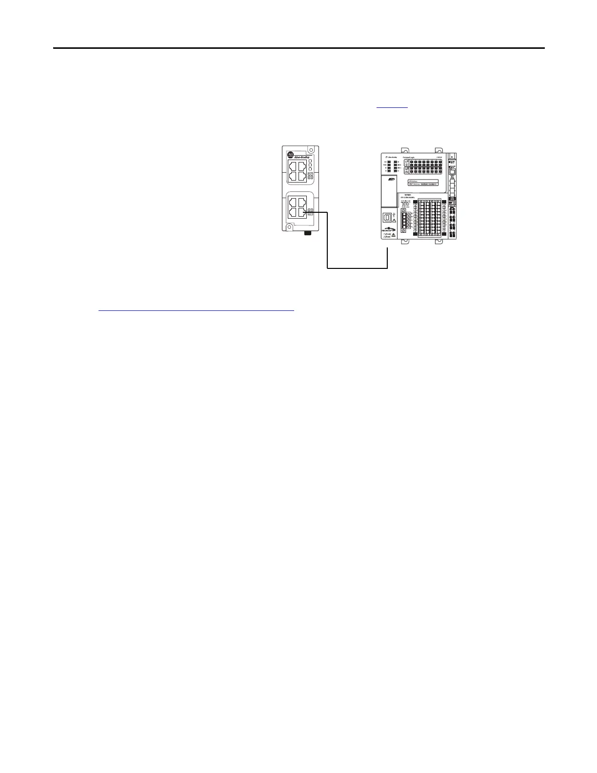
Make EtherNet/IP Network Connections
This section assumes that you installed an EtherNet/IP network as described on page 17 and the network includes a
1783-EMS08T Stratix 6000 Ethernet managed switch.
1. Plug a 1585J-M4TBJM-1, Ethernet cable
(straight-through) into a port on the Stratix
6000 switch.
2. Plug the other end of the Ethernet cable into
one of the Ethernet ports on the bottom of
the controller.
Set the Network IP Address
Once you connect the CompactLogix 5370 L1
controller to an EtherNet/IP network, you must
assign the controller a unique IP address. For information about how to set the network IP address for your controller, see
Chapter 3, Configure the EtherNet/IP Network
on page 43.

 Loading...


