60 Rockwell Automation Publication IASIMP-QS024C-EN-P - August 2014
Chapter 4 Create a Logix Designer Project
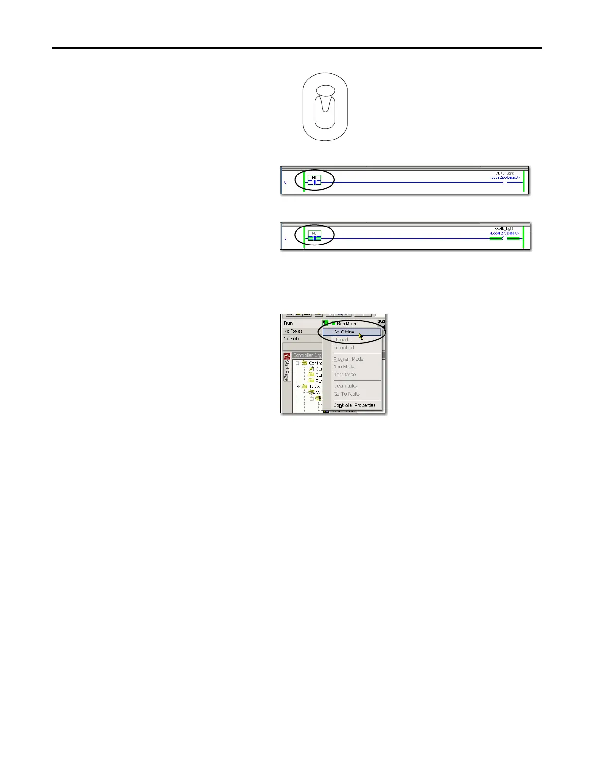
4. Move the mode switch on your controller to
the RUN position.
5. In the Main Routine, select the PB Examine
On instruction.
6. Press Ctrl+T to toggle the state from 0 to 1,
or Off to On.
7. Verify that the status indicator on the digital
output module turns on after you toggle the
state to 1 or On.
8. Press Ctrl+T to toggle the state back to 0 or Off.
9. Go Offline.

 Loading...


