Rockwell Automation Publication 1756-RM100F-EN-P - October 2018 101
Standard Application Conversion Chapter 5
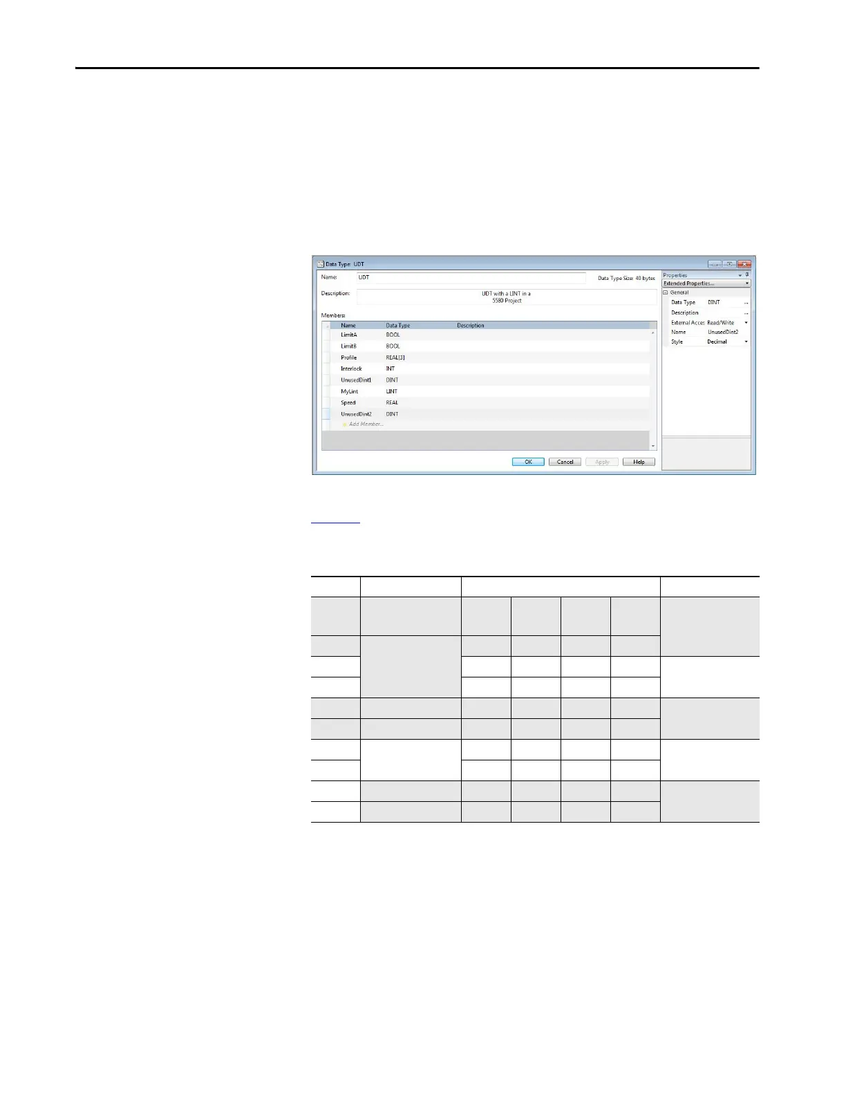
To create a UDT that is the same size in all types of projects, insert additional
data elements so that hidden padding bytes are not necessary.
The following sample UDT illustrates how UnusedDint1 and UnusedDint2
were added to create a UDT with the same size in a Logix Designer project,
version 26 or earlier compared to a Logix Designer project, version 27 or later.
Figure 18 - UDT Sample - Memory Allocation and Alignment OK
Table 1 7 illustrates how this data structure maps in all types of Logix 5000
controller projects:
The concept is the same for nested UDTs. If the lower-level UDT is an 8-byte
type (that is, it contains at least one 8-byte data element), you must align it to
start at an 8-byte boundary.
Table 17 - Memory Map in All Project Types
Word Elements Byte Mapping Table 64 Bit Boundaries
0 Bools and 2 Pad Pad Pad Hidden
SINT
0
1 Profile (Real [3]) Map Map Map Map
2 Map Map Map Map 1
3 Map Map Map Map
4 Interlock (Int) Pad Pad Map Map 2
5 UnusedDint1 Map Map Map Map
6 MyLint (LINT) Map Map Map Map 3
7 Map Map Map Map
8
Speed (REAL) Map Map Map Map 4
9
UnusedDint2 Map Map Map Map
 Loading...


