Rockwell Automation Publication 5069-IN019C-EN-P - October 2018 13
CompactLogix 5480 Controller
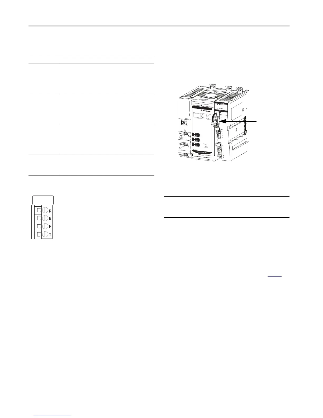
UPS Control Signals
These control signals are used on the UPS Control RTB:
UPS Control RTB Terminals
Install the UPS Control RTB
Install the UPS control RTB even if you do not intend to connect
uninterruptible power to the controller.
1. Hook the bottom of the UPS power RTB on the controller.
2. Push the RTB against the controller until you hear a click.
.
3. Push the RTB handle against the RTB until you hear a click.
Connect UPS Control Signals
1. Verify that all sources of MOD power and SA power are
turned off.
2. Verify the following:
• A 24V DC power supply is connected to the 24V IN
terminals on the UPS.
• A 12V DC battery is connected to the 12V BAT terminals
on the UPS.
For more information, see the example graphic on
page 15.
Signal Description
UPS Ready (R)
An input signal from the UPS to the controller that indicates the UPS is
working and can buffer during a power failure.
The charge level for a UPS to be ready to buffer during a power failure
varies. For example, the 1606-XLS240-UPS power supply must be
greater than 85% charged to be ready.
The letter R indicates the RTB terminal for this signal.
Buffering (B)
An input signal from the UPS to the controller that indicates the UPS
battery is providing power because the external power has failed.
After a preset time (typically 1 minute after power failure), the
controller performs an orderly shutdown by stopping execution and
saving the state of the controller.
The letter B indicates the RTB terminal for this signal.
Battery Fail (F)
An input from the UPS to the controller that indicates the UPS battery
has failed, and the controller cannot operate from stored energy.
In this case, the controller does not attempt to save the state of the
program when the external power fails. The controller issues an alarm
if a UPS was previously attached and ready to buffer.
The letter F indicates the RTB terminal for this signal.
Inhibit (I)
An output signal from the controller to the UPS that disables the UPS
signal output. The INHIBIT signal is triggered after data is backed up
and the system is ready to shut down.
The letter I indicates the RTB terminal for this signal.
IMPORTANT The UPS terminal labels in this section represent the labels on
a 1606-XLS240-UPS power supply. Your UPS terminals can be
labeled differently.
UPS Control RTB

 Loading...


