14 Rockwell Automation Publication 5069-IN019C-EN-P - October 2018
CompactLogix 5480 Controller
Connect to the MOD Power RTB from a UPS
1. Daisy chain the wires from these connections on the UPS:
• 24V OUT (+)
• Ready (1)
• Buffering (3)
• Battery Fail (5)
• Inhibit (7)
2. Connect one wire to each (+) terminal on the MOD power
RTB, as shown in the example graphic on
page 15.
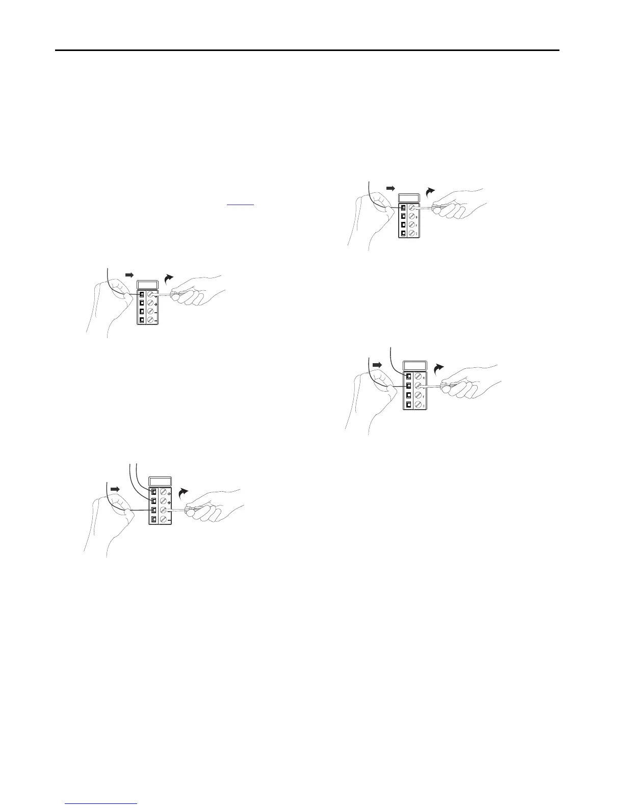
a. Insert the wire into the terminal.
b. Turn the screwdriver to close the terminal on the wire.
The screw torque is 0.4 N•m (3.5 lb•in).
3. Daisy chain a wire that is connected to the 24V OUT (–)
terminal on the UPS and a second wire.
4. Connect one wire to each (–) terminal on the MOD
power RTB.
a. Insert the wire into the terminal.
b. Turn the screwdriver to close the terminal on the wire.
The screw torque is 0.4 N•m (3.5 lb•in).
Connect to the UPS Control RTB from a UPS
1. Connect a wire from the Ready (2) connection on the UPS to
the UPS Ready terminal on the UPS control RTB.
a. Insert the wire into the terminal.
b. Turn the screwdriver to close the terminal on the wire.
The screw torque is 0.4 N•m (3.5 lb•in).
2. Connect a wire from the Buffering (4) connection on the UPS
to the Buffering terminal on the UPS control RTB.
a. Insert the wire into the terminal.
b. Turn the screwdriver to close the terminal on the wire.
The screw torque is 0.4 N•m (3.5 lb•in).

 Loading...


