Rockwell Automation Publication 5069-IN019C-EN-P - October 2018 15
CompactLogix 5480 Controller
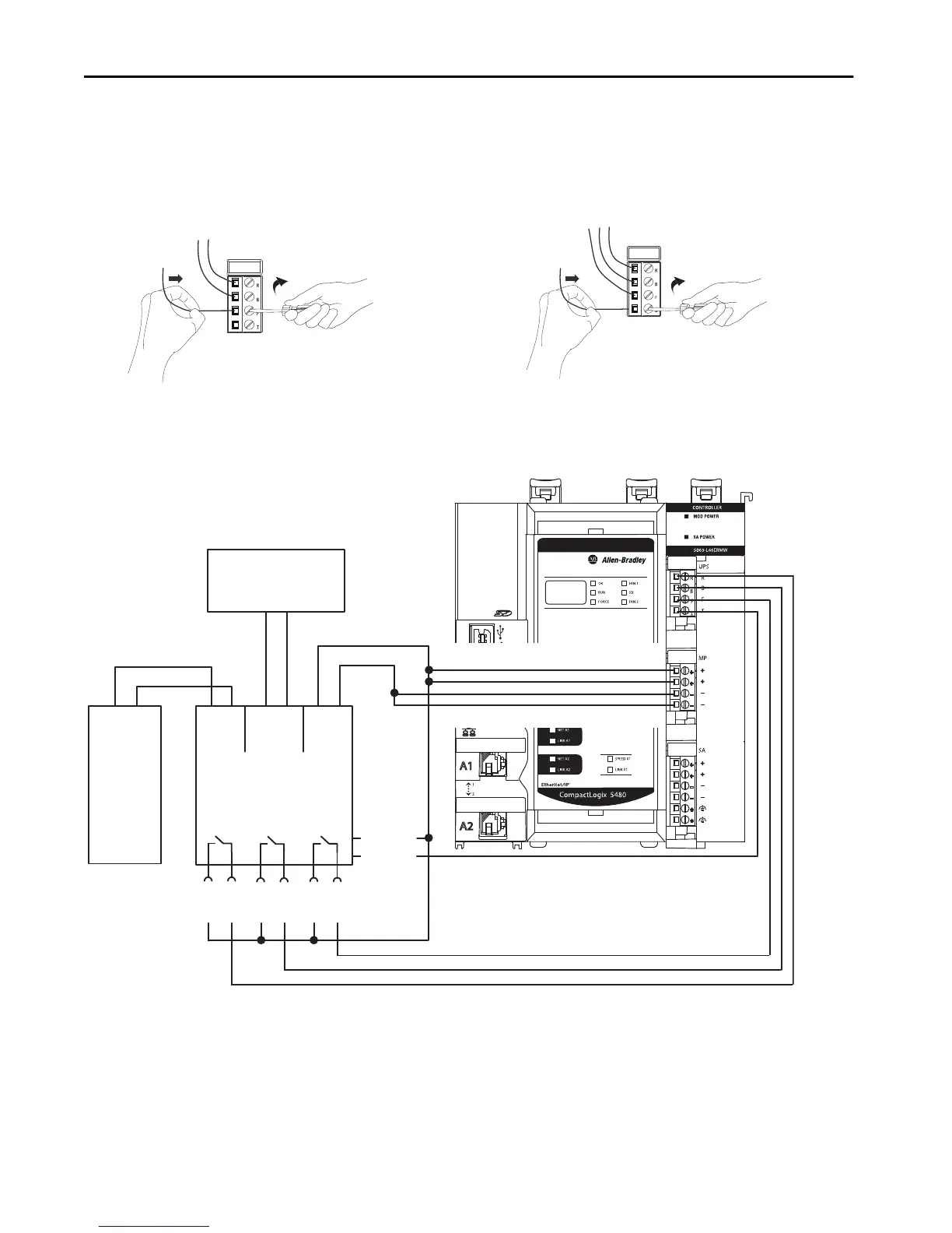
3. Connect a wire from the Battery Fail (6) connection on the
UPS to the Battery Fail terminal on the UPS control RTB.
a. Insert the wire into the terminal.
b. Turn the screwdriver to close the terminal on the wire.
The screw torque is 0.4 N•m (3.5 lb•in).
4. Connect a wire from the Inhibit (8) connection on the UPS to
the Inhibit terminal on the UPS control RTB.
a. Insert the wire into the terminal.
b. Turn the screwdriver to close the terminal on the wire.
The screw torque is 0.4 N•m (3.5 lb•in).
This diagram shows a 1606-XLS240-UPS power supply battery that is connected to a CompactLogix 5480 controller.
UPS Ready
Buffering
Battery Fail
Inhibit
(7) Inhibit +
(8) Inhibit –
24V DC
Power
Supply
Ready
(1) (2)
+–
+– +– +–
NLPE
Buffering
(3) (4)
Battery Fail
(5) (6)
12V DC Battery
(for example, 1606-XLSBATASSY1)
+–
DC-UPS
(1606-XLS240-UPS)
24V
IN
12V
BAT
24V
OUT

 Loading...


