Installing Your Module
Chapter 2
2-5
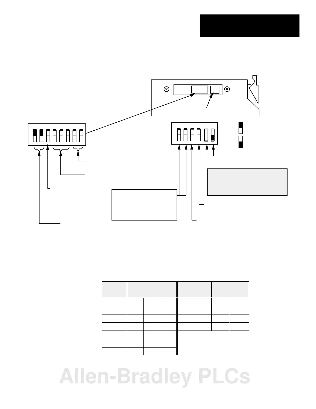
Figure 2.4
Module
Switch Assembly Settings for PLC2 Family Processors
12345678
O
N
O
F
F
O
N
O
F
F
1234
First I/O group number
(Table 2.C)
I/O rack number
(Table 2.C)
Address Switch Assembly
(S1)
Switch Assembly
(S2)
SD always OFF
SD2 without complementary I/O always OFF
SD2 with complementary I/O
ON Primary chassis
OFF Complementary chassis
Pressed in at top
Closed (ON)
Pressed in at bottom
Open (OFF)
Maximum I/O
chassis distance
SD
always ON
SD2 without complementary I/O
always ON
SD2 with complementary I/O
ON Primary chassis
OFF Complementary chassis
Always ON
56
Link Response ON for series B emulation
Scan on for all but last 4 slots
off for all slots
OFF for unrestricted
Switch Position
1 2
57.6K Baud 10,000ft
1
15.2K Baud 5,000ft
Not Used
Not Used
10798I
ATTENTION: Link response switch must
be ON when using the following scanner
modules:
1772SD2
ON OFF
OFF OFF
ON ON
ONOFF
Off
Table 2.C
I/O
Rack Number and First I/O Group Switch Selections for the Address
Switch Assembly S1 (PLC2 Family Processors)
I/O Rack
Number
Switch Selections
4 5 6
First I/O Group
Number
Switch Selections
7 8
1 On On On 0 On On
2 On On Off 2 On Off
3 On Off On 4 Off On
4 On Off Off 6 Off Off
5 Off On On
6 Off On Off
7 Off Off On
Allen-Bradley PLCs
 Loading...


