Chapter 3
Addressing Modes for Your Remote I/O
3-3
Definition: The processor addresses two I/O module slots as one I/O
group.
Concept: Each physical 2-slot I/O group is represented by a word in the
input image table and a word in the output image table. Each input
terminal corresponds to a bit in the input image table word and each output
terminal corresponds to a bit in the output image table word.
The maximum number of bits available for one 2-slot I/O group is 32: 16
bits in the input image table and 16 bits in the output image table. The
type of module you install (either 8 or 16-point I/O) determines the number
of bits in the words that are used.
You select 2-slot addressing by setting switches 5 and 6 of the I/O chassis
backplane switch assembly to the OFF position.
I/O Module Combinations
The combination of I/O modules you can use depends on the addressing
method and I/O chassis you select.
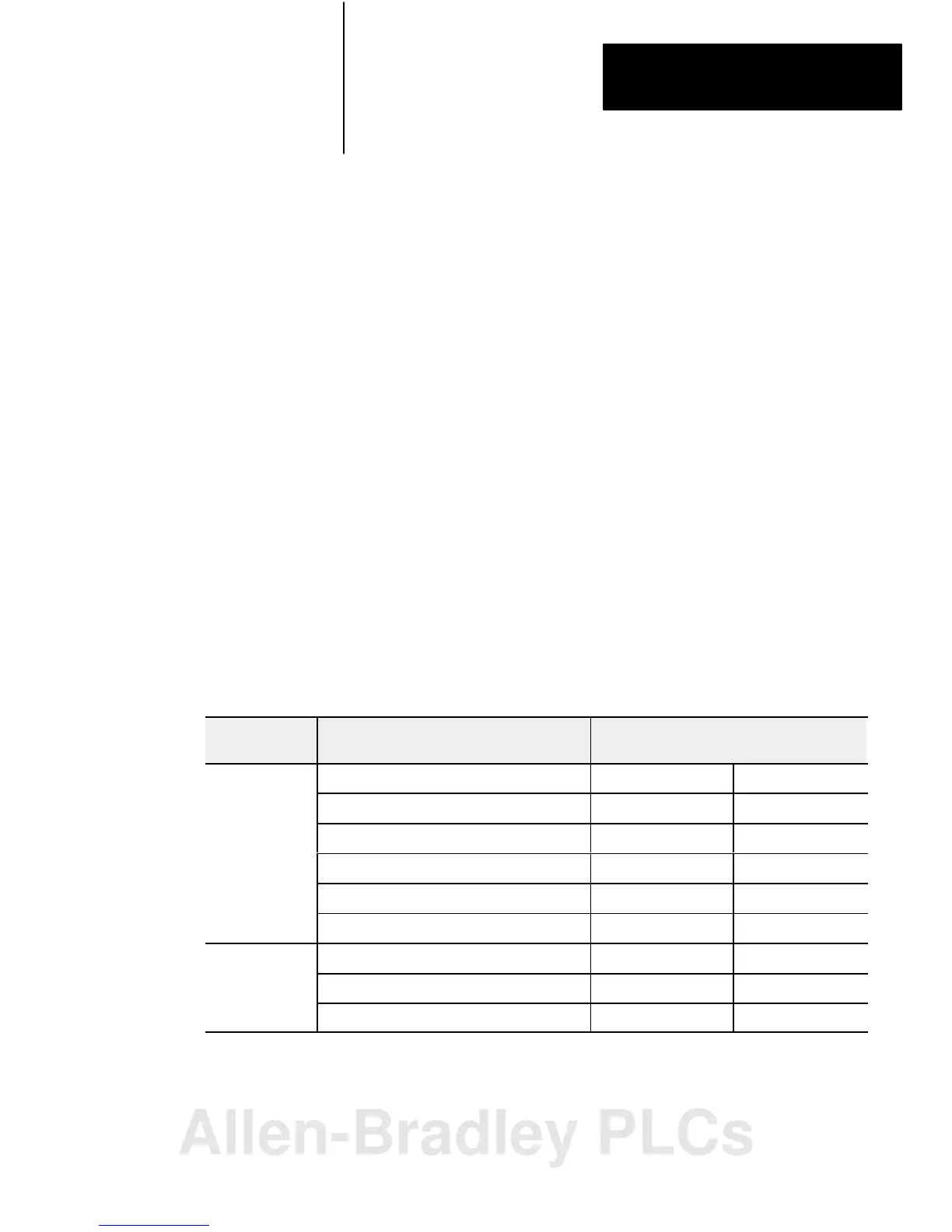
Table 3.A lists acceptable I/O module combinations with 2-slot addressing.
Table 3.A
I/O
Module Combinations With 2slot Addressing
I/O Chassis
Series
I/O Module Combinations Per I/O Group
Data Table Bits Used
Input Image Table Output Image Table
A, B 2 8point input modules 16 0
2 8point output modules 0 16
1 8point input and output module 8 8
1 8point input and 1 block transfer output module 16 8
1 block transfer and 1 8point output module 8 16
2 block transfer modules 16 16
B or later only 1 16point input and output module 16 16
1 16point and 1 8point output module 16 8
1 8point input and 1 16point output module 8 16
2Slot Addressing
Allen-Bradley PLCs
 Loading...


