Addressing Modes for Your Remote I/O
Chapter 3
3-12
When using single-slot block-transfer modules:
The right slot of the primary I/O group can be another single-slot
block-transfer module, or an 8-point input or output module.
The left slot of the complementary I/O group must be empty.
You can place an 8-point output module in the right slot of the
complementary I/O group; this slot must be empty if the
corresponding slot in the primary I/O group is a single-slot
block-transfer module.
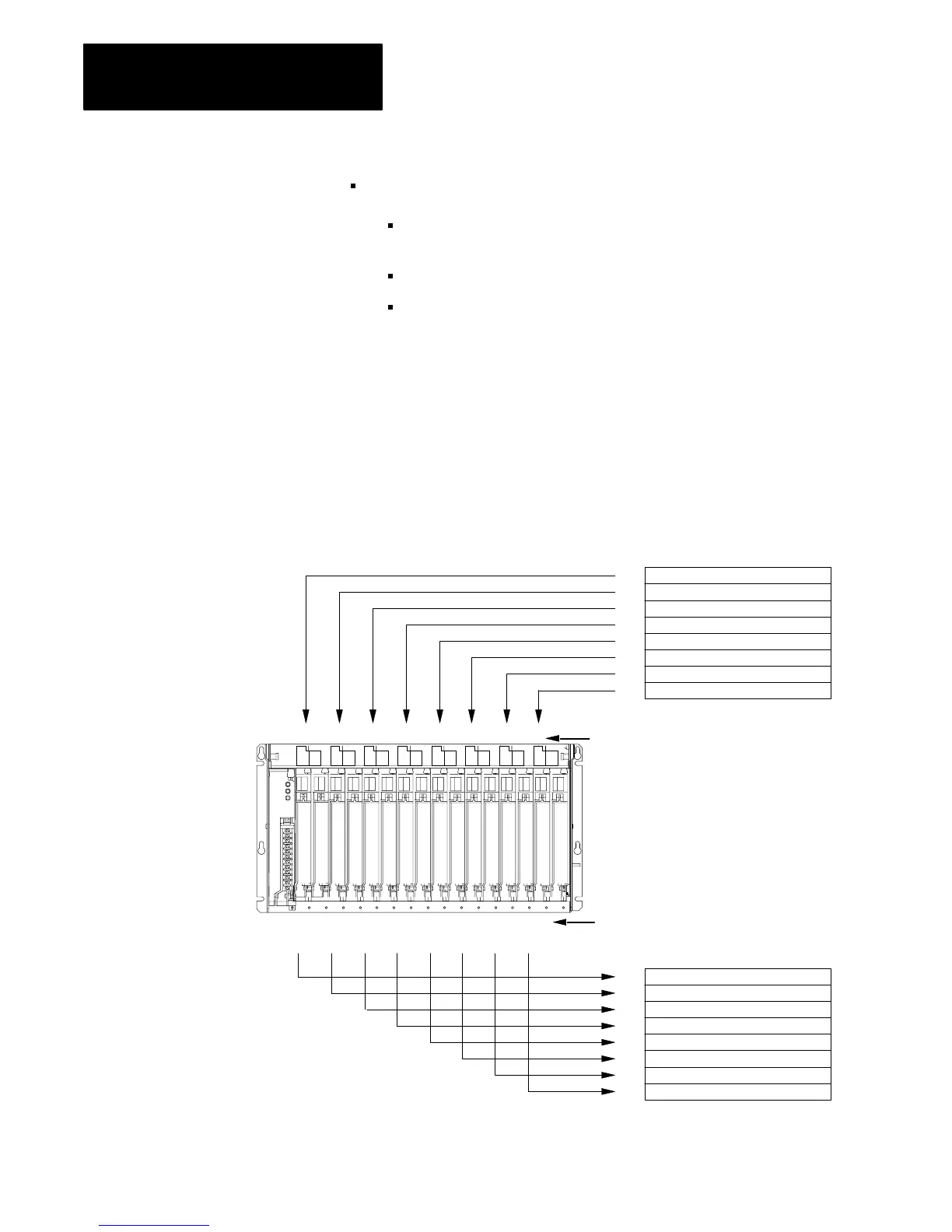
When you select 2-slot addressing, each pair of slots (one I/O group) is
assigned to the corresponding pair of words in the input and output image
tables. You assign one I/O rack number to eight I/O groups (Figure 3.10).
Figure 3.10
I/O
Image T
able and Corresponding Hardware for One Assigned Rack
Number with 2slot Addressing
IO IO IO IO IO IO IO IO
0
1
2
3
4
5
6
7
0
1
2
3
4
5
6
7
01234567
Word #
Word #
Output Image Table
Input Image Table
14966
NOTE: Modules can also be
installed like this: I O O I
I/O
Group Designation
Input/Output Designation
An I/O chassis containing 16point modules
0 1234567
 Loading...


