Troubleshooting
Chapter 4
4-2
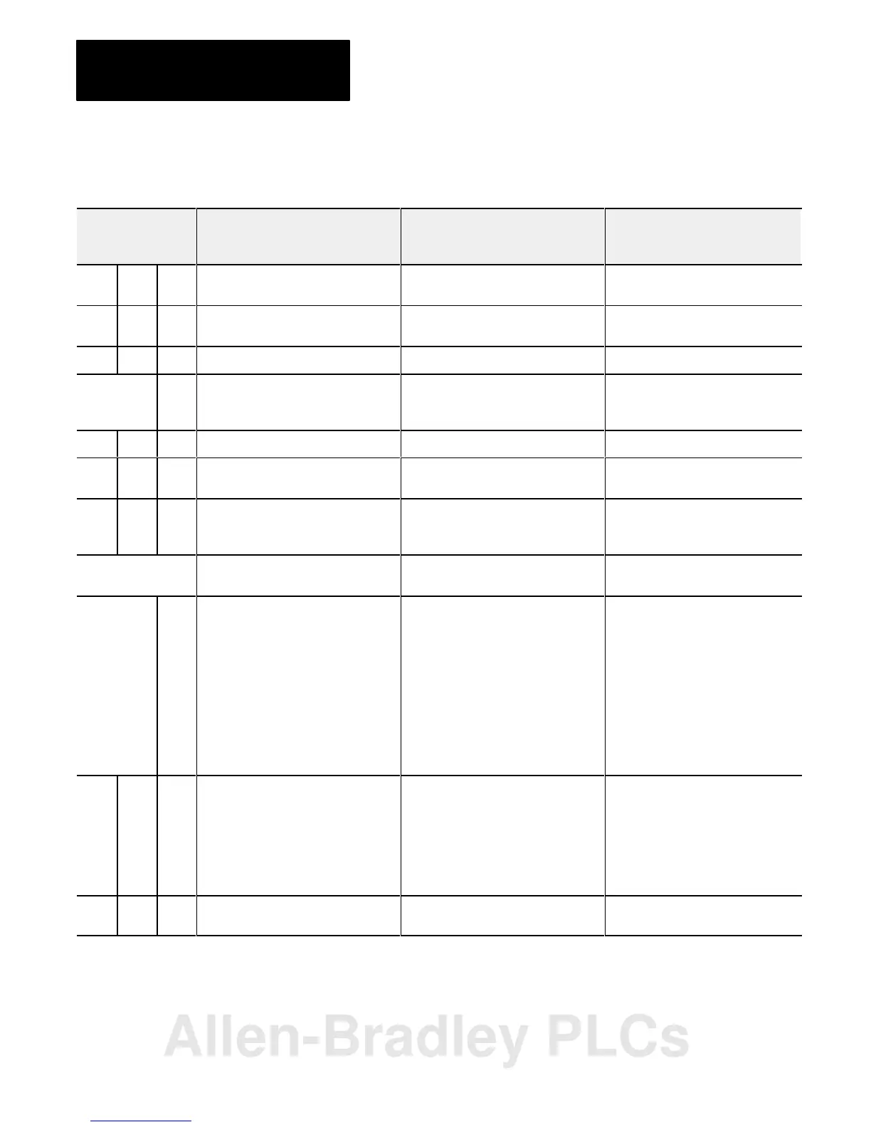
Table 4.A
Remote I/O System Troubleshooting Guide
Indicators
Active Adapter I/O
Fault Rack
Description Probable Cause Recommended Action
On Off Off Normal indication; remote adapter is fully
operational
Off On Off Adapter crash. RAM memory fault.
Watchdog timeout
Cycle power. Replace module if
problem reoccurs.
On Blink Off Module placement error I/O module in incorrect slot. Place module in correct slot in chassis.
Blink in unison Off Incorrect starting I/O group number Error in starting I/O group number or I/O
rack address
Check dipswitch settings. Refer to table
3.B to verify acceptable beginning I/O
group number; set switches correctly
On On On Module not communicating Incorrect baud rate setting Check dipswitch setting
Off On On Module not communicating Scan switch set for "all but last 4 slots" in
1/4 rack
Reset scan switch setting
Blink Off Off Remote adapter not actively controlling
I/O (scanner to adapter communication
link is normal)
4
Processor is in program or test mode
Scanner is holding adapter module in
fault mode
Fault should be cleared by I/O scanner
LEDs sequence on/off
from top to bottom
Module not communicating Another remote I/O adapter with the
same address is on the link.
Correct the address.
Blink
alternately
Off Adapter module not actively controlling
I/O
2
Adapter module in processor restart
lockout mode (adapter to scanner link is
normal)
5
Processor restart lockout switch on
chassis backplane switch assembly on
1
Depress reset button to clear lockout
feature or cycle power; if after repeated
attempts indicators are still blinking,
check:
• pushbutton not wired properly to
field wiring arm
• wiring arm not connected to
adapter module
• adapter module was reset by
processor/scanner, then
immediately faulted
Off Off On I/O chassis fault.
2
No communication on
link.
Problem exists between:
• adapter and module in chassis; the
module will stay in fault mode until
fault is corrected
• shorted printed circuit board runs on
backplane or I/O module
Cycle power to the chassis to clear a
problem resulting from high noise
3
• remove and replace all I/O
modules one at a time
• if problem does not clear,
something is wrong in chassis or I/O
module
Blink Off On Communication on link. Chassis
violation.
Possible shorted backplane in chassis.
Excessive noise on backplane.
6
Check chassis, Replace chassis as
necessary.
Allen-Bradley PLCs
 Loading...


