4 FLEX I/O ControlNet Adapter Modules
Publication 1794-IN128E-EN-P - March 2011
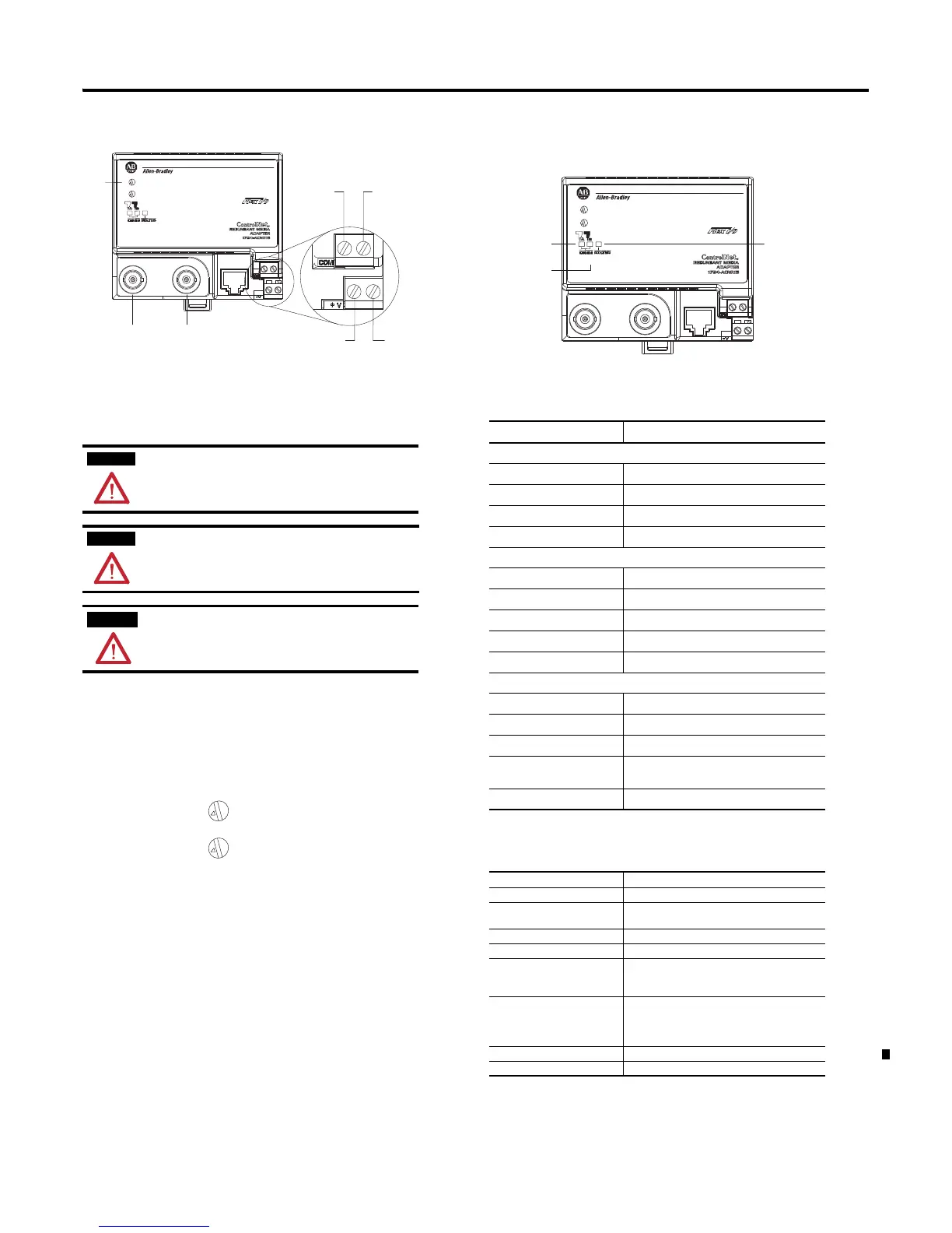
Connecting Wiring
1. Connect the ControlNet network cable to connector, terminal A.
2. For 1794-ACNR15, 1794-ACNR15XT only: Connect the redundant
ControlNet network cable to connector B.
3. Connect +V DC power to the left side of the lower connector, terminal D.
4. Connect -V common to the left side of the upper connector, terminal C.
5. Connections E and F are used to pass +V DC power (F) and -V common
(E) to the next module in the series (if required).
6. Set the network address using the selection dials G. Valid settings range
from 01…99.
Indicators
The module has LED indicators to specify its status and aid the user in
troubleshooting.
Specifications
If you connect or disconnect the ControlNet cable with power applied
to this module or any device on the network, an electrical arc can
ocur. This could cause an explosion in hazardous installations. Be
sure that power is removed or the area is nonhazardous before
proceeding.
If you connect or disconnect wiring while the field side power is on,
an electrical arc can occur. This could cause an explosion in
hazardous location installations. Be sure that power is removed or
the area is nonhazardous before proceeding.
• When connecting wiring, torque terminal screws C, D, E and F
to 0.8 Nm (7 lb-in).
• Power wiring must be less than 10 meters (32.8 ft) in length.
• Do not wire more than 2 conductors on any single terminal.
0
1
2
3
4
5
6
7
8
9
0
1
2
3
4
5
6
7
8
9
X10
X1
0
1
2
3
4
5
6
7
8
9
0
1
2
3
4
5
6
7
8
9
X10
X1
LED Indicators
LED Indications Probable Cause
Comm A and Comm B Simultaneously
Off No power, or reset
Red Adapter inoperative
Red/Green – flashing alternately Adapter self-test
Red/Off – flashing alternately Bad node configuration (duplicate address)
Comm A or Comm B (individually)
Off Channel disabled
Green Channel operational
Flashing green/Off Temporary network errors
Flashing red/Off Cable fault, broken cable, redundancy warning
Flashing red/green Bad network configuration
Status Indicator
Off No power
Flashing green/off On-line but not connected
Green On-line, link OK, connected
Flashing red I/O module removed, wrong I/O module inserted,
FLASH program update in progress
Red Critical – adapter failure
General
Attribute Value
I/O capacity 8 modules
Supply voltage Input: 19.2…31.2V DC, 400 mA
Output: 5V DC, 640 mA
Inrush current 14 A for 2 ms
Communication rate 5 Mbps
Indicators I/O Status – red/green
Comm A – red/green
Comm B – red/green
Isolation voltage 50V (continuous), Basic Insulation Type
Type tested @ 860 V AC for 60 s, power to system,
power to ControlNet, and ControlNet to system
No isolation between ControlNet channels
Power dissipation, max 3.4 W @ 19.2V DC
Terminal screw torque 0.8 Nm (7 lb-in.)
0
1
2
3
4
5
6
7
8
9
0
1
2
3
4
5
6
7
8
9
X10
X1
 Loading...


