Rockwell Automation Publication 1756-RM012B-EN-P - April 2018 41
Characteristics of Safety Tags, the Safety Task, and Safety Programs Chapter 5
From a safety architecture perspective, using single channel means that the
hardware fault tolerance (HFT) is zero. When the HFT is zero, there are
guidelines that state that faults must be detected and the safety function must
be taken to a safe state within the process safety time. An exception applies if
the diagnostic test rate is 100 times the demand rate. If using safety I/O
modules in single channel SIL 2 applications, the following need be
considered:
• Input or output channel must be configured for Safety Pulse Test
• Process Safety Time greater than 600 ms (the typical safety I/O pulse
test interval) or the demand rate must be less than one demand per
minute (for example, one per hour)
CompactBlock Guard I/O (1791 series), ArmorBlock Guard I/O (1732
series), POINT Guard I/O (1734 series), and Compact 5000 I/O Safety
(5069 series) safety input modules support single-channel SIL 2 (see preceding
considerations) and dual-channel SIL 3 safety input circuits. Because these
modules are rated for both SIL 2 and SIL 3 operation, you can mix SIL 2 and
SIL 3 circuits on the same module.
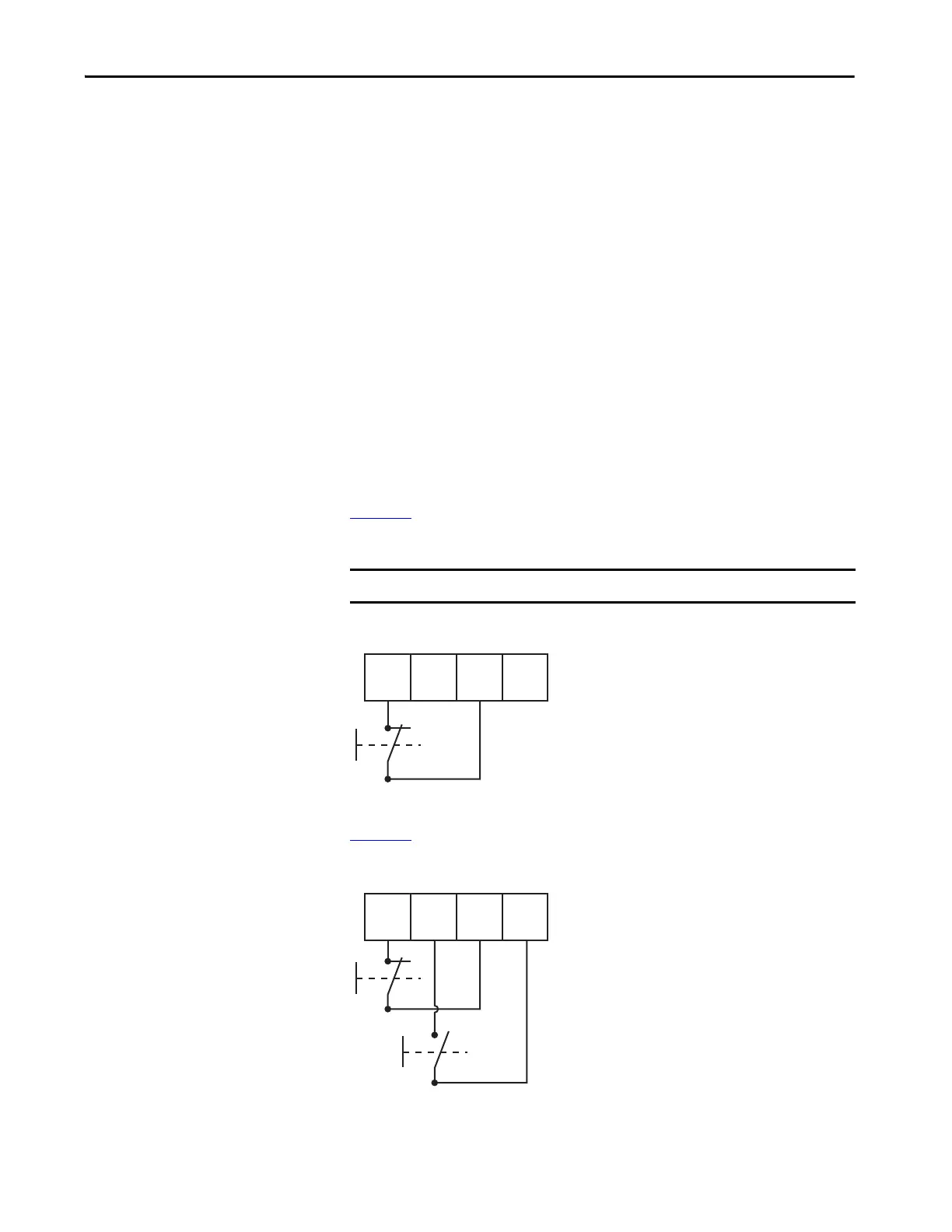
Figure 13
shows how to wire SIL 2 safety circuits to Guard I/O safety input
modules.
Figure 13 - Example Input Wiring
If you have two SIL 2 safety circuits, you can add a second as shown in
Figure 14
.
Figure 14 - Example Input Wiring in Pairs
IMPORTANT The test source must be configured for pulse testing.

 Loading...


