Rockwell Automation Publication 440C-WD001C-EN-P - June 2015 11
Cat 1 Stop with Guardlocking Interlock (TLS-ZR or 440G-LZ) Chapter 1
Connected Components
Workbench Software
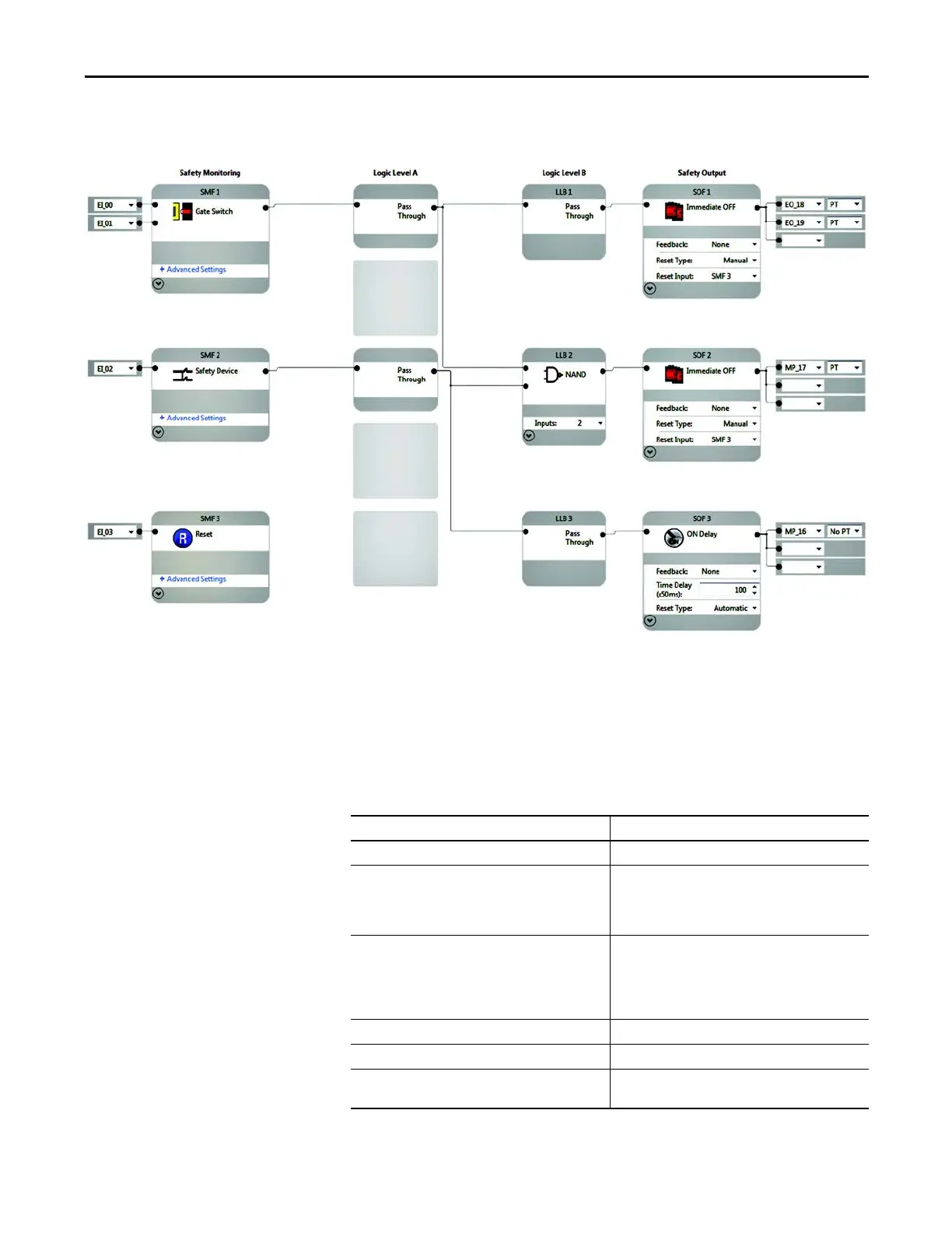
Figure 3 - Connected Components Workbench Example
Circuit Status
The gate switch is closed and locked. The safety signals to the PF525 drive are off,
and the drive is disabled. The motor is off.
Operational Sequence
Table 2 - Operational Sequence
Action Taken Results
1. Momentarily press the reset button. The safety outputs at terminal 17, 18 and 19 turn ON.
2. Press the drive Start button. The motor turns ON. The drive can now be used for normal
producti
on processes.
The speed of the motor is controlled by the Drive Pot,
located on the front of the PF525.
3. Rotate the Unlock request to the Unlock (closed)
position.
The power is immediately removed from terminals 17,
and the drive executes a ramp to stop command in 3
seconds (P042 is configured for 3s).
After a 5 second delay, the gate switch is unlocked and the
safety outputs to the drive open.
4. Open the gate switch. The operator can access the hazard area.
5. Close the gate.
6. Rotate the Unlock switch to the locked (open) position. This locks the gate and the safety system is ready for reset.
Go to Step 1.

 Loading...


