22 Rockwell Automation Publication 2094-RM002B-EN-P - May 2012
Chapter 3 Safe Torque-off I/O Signals
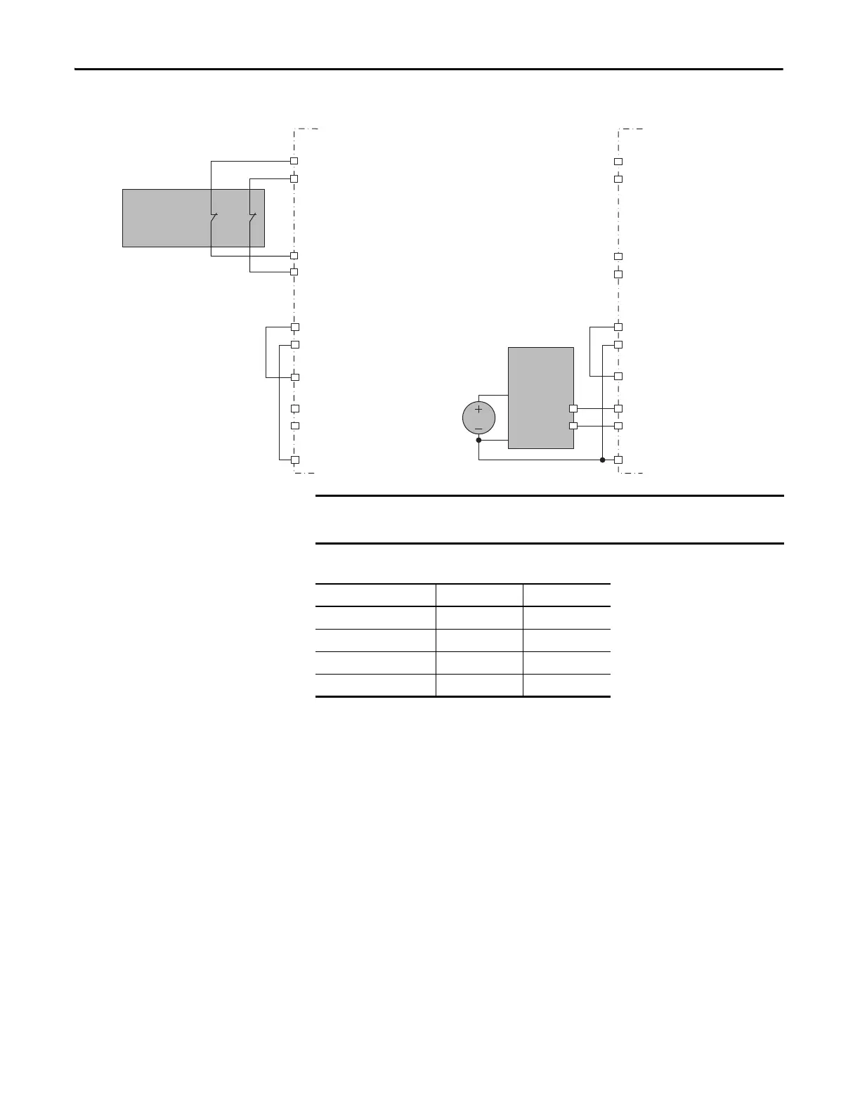
Figure 8 - Safety Input Wiring Examples
Table 4 - IOD Connector Input Terminals
Short-circuits of the input loop to ground or 24V will be detected. For
dual-channel inputs, cross loops will also be detected.
Test_Out_0 (IOD-27)
Test_Out_1 (IOD-28)
Dual-channel
Equivalent
Safety Device
Light Curtain
or
Safety Mat
Drive
Drive
SS_IN_CH2 (IOD-23)
SS_IN_CH3 (IOD-24)
Test_Out_0 (IOD-27)
Test_Out_1 (IOD-28)
SS_IN_CH2 (IOD-23)
SS_IN_CH3 (IOD-24)
24VPWR (IOD-14)
24VCOM (IOD-15)
SPWR (IOD-17)
SPWR (IOD-17)
SCOM (IOD-18)
SCOM (IOD-18)
SS_IN_CH0 (IOD-19)
SS_IN_CH1 (IOD-20)
SS_IN_CH0 (IOD-19)
SS_IN_CH1 (IOD-20)
OSSD1
OSSD2
24V DC
24VPWR (IOD-14)
24VCOM (IOD-15)
Cross wiring of Test Outputs to Inputs is not allowed. For example, do not
connect TEST_OUT_0 to Input 1 or TEST_OUT_1 to Input 0.
Safe Stop Function Signal IOD Pin
Input 0 = Channel 0 SS_IN_CH0 IOD-19
Input 1 = Channel 1 SS_IN_CH1 IOD-20
Input 2 = Channel 2 SS_IN_CH2 IOD-23
Input 3 = Channel 3 SS_IN_CH2 IOD-24

 Loading...


