10 Micro820 20-Point Programmable Controllers
Publication 2080-IN009B-EN-P - April 2014
2. Push the DIN rail latch back into the latched position.
To remove your controller from the DIN rail, pry the DIN rail latch downwards until it is in the
unlatched position.
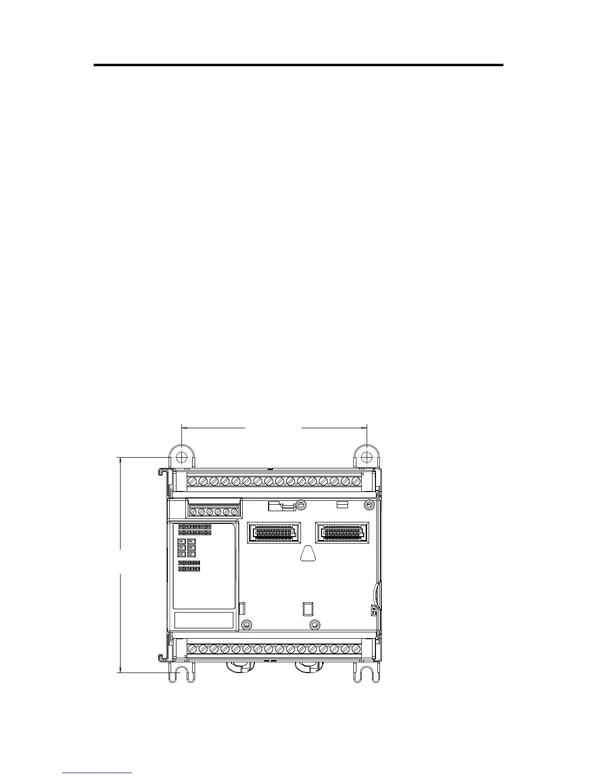
Panel Mounting
The preferred mounting method is to use four M4 (#8) screws per module. Hole spacing
tolerance: ±0.4 mm (0.016 in.).
Follow these steps to install your controller using mounting screws.
1. Place the controller against the panel where you are mounting it. Make sure the
controller is spaced properly.
2. Mark drilling holes through the mounting screw holes and mounting feet then remove
the controller.
3. Drill the holes at the markings, then replace the controller and mount it. Leave the
protective debris strip in place until you have finished wiring any other devices.
Panel Mounting Dimensions
46204
86 mm
(3.39 in.)
100 mm
(3.94 in.)
 Loading...


