20 Micro820 20-Point Programmable Controllers
Publication 2080-IN009B-EN-P - April 2014
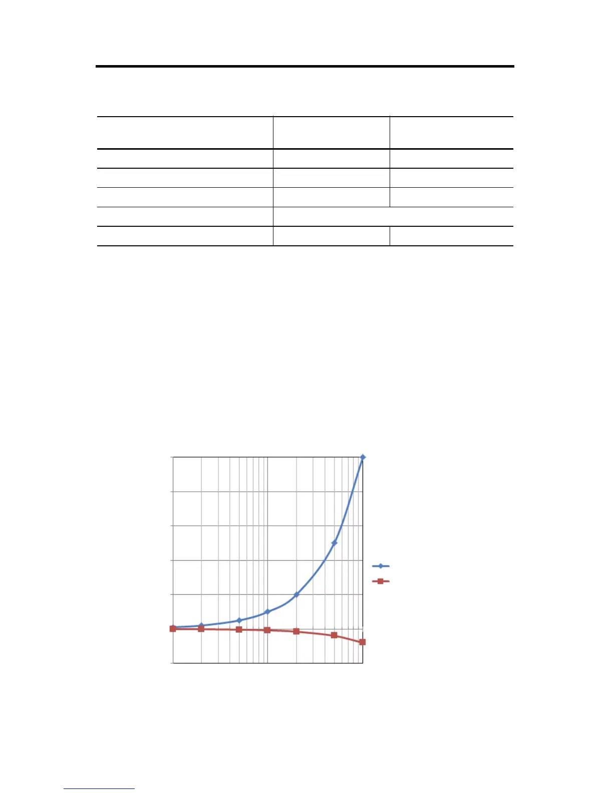
PWM Output Duty Cycle Error
Turn On/Off time for the Micro820 controllers for the PWM output port is 0.2 µs and 2.5 µs
max, respectively. Duty cycle error is:
Positive error = 2.5 µs * F
Negative error = -0.2 µs * F
The plot below shows duty cycle error vs. frequency.
To get the duty cycle error at a certain frequency, for example, the user sets frequency to 20 KHz,
and sets duty cycle to 30% in Connected Components Workbench, then actual duty cycle is
.
Controller current, max total 3 A –
Turn-on time, max 0.1 ms 0.2 μs
Turn-off time, max 1.0 ms 2.5 μs
Response time, max 10 ms
Frequency rate NA 2%
(1)
High speed output operation is greater than 5 Khz.
DC Output Specifications for 2080-LC20-20QBB(R)
Attribute Standard Outputs
(Outputs O-00…O-05)
High Speed Output
(1)
(Output O-06)
Error (Percentage)
0.25
0.2
0.15
0.1
0.05
0.0
-0.05
1000
10000
100000
Positive Error
Negative Error
 Loading...


