14 Micro820 20-Point Programmable Controllers
Publication 2080-IN009B-EN-P - April 2014
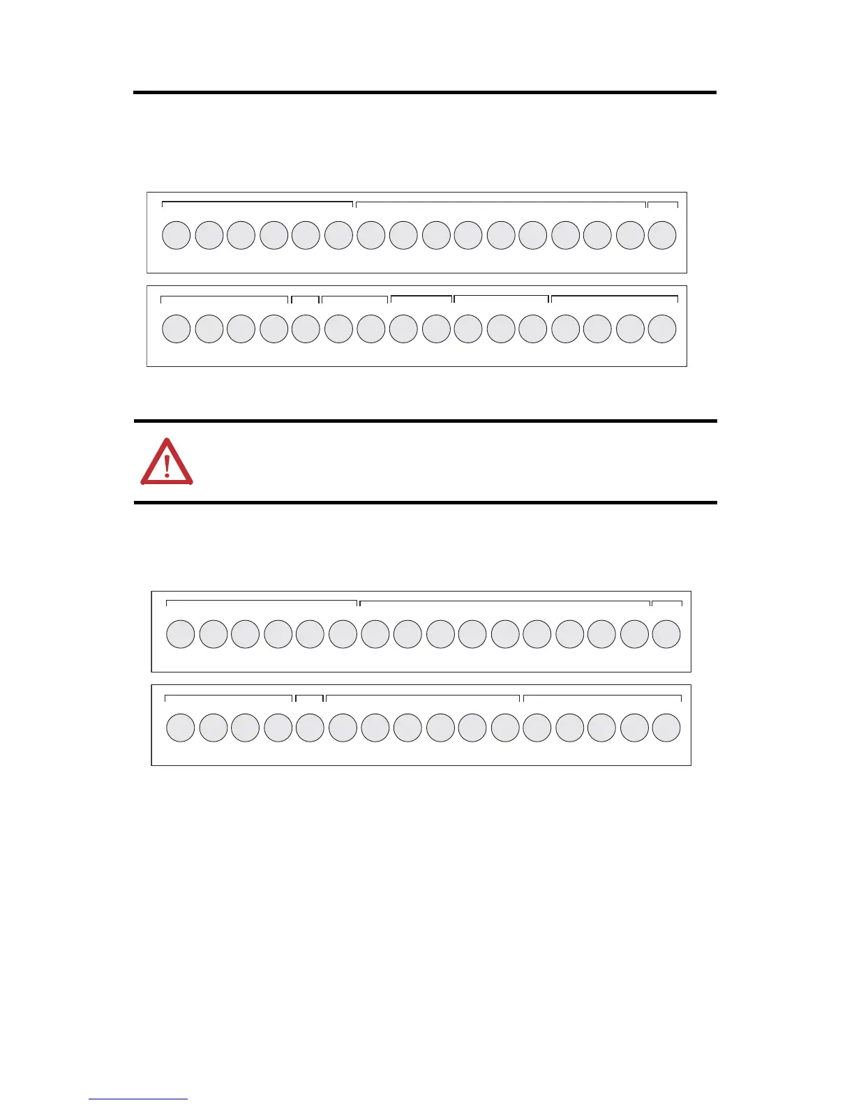
2080-LC20-20AWB / 2080-LC20-20AWBR / 2080-LC20-20QWB / 2080-LC20-20QWBR
2080-LC20-20QBB / 2080-LC20-20QBBR
ATTENTION: For 2080-LC20-20AWB/R, inputs 0…3 are limited to 24V DC. All
other inputs (4...11) are limited to 120V AC.
-DC24
+DC10 I-00
I-01
I-02
I-03
COM0
I-04
I-05
I-08
I-07
123456789101112
+DC24 -DC24
VO-0-DC24
NU
CM0
O-00
CM1 CM2
O-01
O-03
O-02
123456789101112
I-10
I-09
NU
I-11
13 14 15 16
O-04
CM3
O-06
O-05
13 14 15 16
I-06
46212
Input Terminal Block
Output Terminal Block
-DC24
+DC10 I-00
I-01
I-02
I-03
COM0
I-04
I-05
I-08
I-07
123456789101112
+DC24 -DC24
VO-0-DC24
NU
+CM0
O-00
O-01 O-03
O-02
+CM1
-CM0
123456789101112
I-10
I-09
NU
I-11
13 14 15 16
O-05
O-04
-CM1
O-06
13 14 15 16
I-06
Input Terminal Block
Output Terminal Block
46211
 Loading...


