Micro820 20-Point Programmable Controllers 9
Publication 2080-IN009B-EN-P - April 2014
Mounting Dimensions and DIN Rail Mounting
Module Spacing
Maintain spacing from objects such as enclosure walls, wireways and adjacent equipment. Allow
50.8 mm (2.0 in.) of space on all sides for adequate ventilation. If optional accessories/modules
are attached such as the optional power supply, 2080-PS120-240VAC, make sure that there is
50.8 mm (2 in.) of space on all sides after attaching the optional parts.
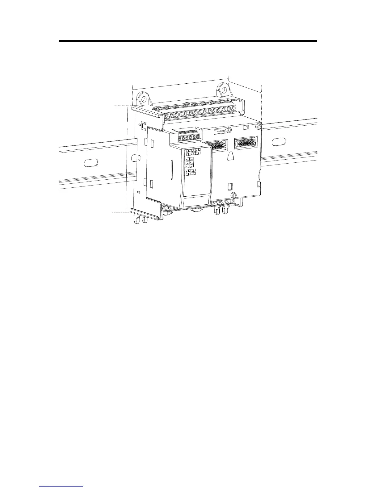
DIN Rail Mounting
The module can be mounted using the following DIN rails: 35 x 7.5 mm and 35 x 15 mm (EN
50 022 - 35 x 7.5 and EN 50 022 - 35 x 15).
Before mounting the module on a DIN rail, use a flat-blade screwdriver in the DIN rail latch and
pry it downwards until it is in the unlatched position.
1. Hook the top of the DIN rail mounting area of the controller onto the DIN rail, and
then press the bottom until the controller snaps onto the DIN rail.
For environments with greater vibration and shock concerns, use the panel
mounting method, instead of DIN rail mounting.
46253
Mounting dimensions do not include mounting feet or DIN rail latches.
Measurements are in millimeters (inches).
104 (4.09)
75 (2.95)
90 (3.54)
 Loading...


