Micro820 20-Point Programmable Controllers 13
Publication 2080-IN009B-EN-P - April 2014
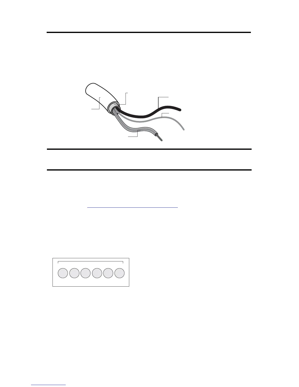
Grounding Your Analog Cable
Use shielded communication cable (Belden #8761). The Belden cable has two signal wires (black
and clear), one drain wire, and a foil shield. The drain wire and foil shield must be grounded at
one end of the cable.
Wiring Your Plug-In Modules
Wiring diagrams for your Micro800 plug-in modules are available in the Rockwell Automation
Literature Library, http://rockwellautomation.com/literature
.
Wire the Controller
Serial Port Terminal Block
Do not ground the drain wire and foil shield at both ends of the cable.
Foil Shield
Black Wire
Drain Wire
Clear Wire
44531
Insulation
D-
D+ G
Rx
Tx
12345
6
G
46213
(View into terminal block)
Pin 1 RS485 Data +
Pin 2 RS485 Data -
Pin3 RS485 Ground
(1)
Pin 4 RS232 Receive
Pin 5 RS232 Transmit
Pin 6 RS232 Ground
(1)
(1)
Non-isolated.

 Loading...


