86 Rockwell Automation Publication 2080-UM002K-EN-E - March 2019
Chapter 7 Motion Control
Sample Motion Wiring Configuration on 2080-LC30-xxQVB / 2080-LC50-xxQVB /
2080-LC70-xxQVB
Servo/Drive Ready INPUT The input signal that indicates Servo/Drive is
ready to receive PTO pulse and direction
signal from controller.
No moving function blocks can be issued to
an axis before the axis has this signal ready if
this signal is Enabled in the motion axis
configuration or axis properties page.
Can be shared
with more
than one drive
In-Position signal
(from Servo/motor)
INPUT The input signal that indicates the moving
part is in the commanded position. This
signal has to be Active after the moving part
reaches the commanded position for
MoveAbsolute and MoveRelative function
blocks.
For MoveAbsolute and MoveRelative
function blocks, when In_Position is enabled,
the controller will report an error
(EP_MC_MECHAN_ERR) if the signal is not
active within five seconds when the last PTO
pulse sent out.
Not Shared
Home Marker INPUT This signal is the zero pulse signal from the
motor encoder. This signal can be used for
fine homing sequence to improve the homing
accuracy.
Not Shared
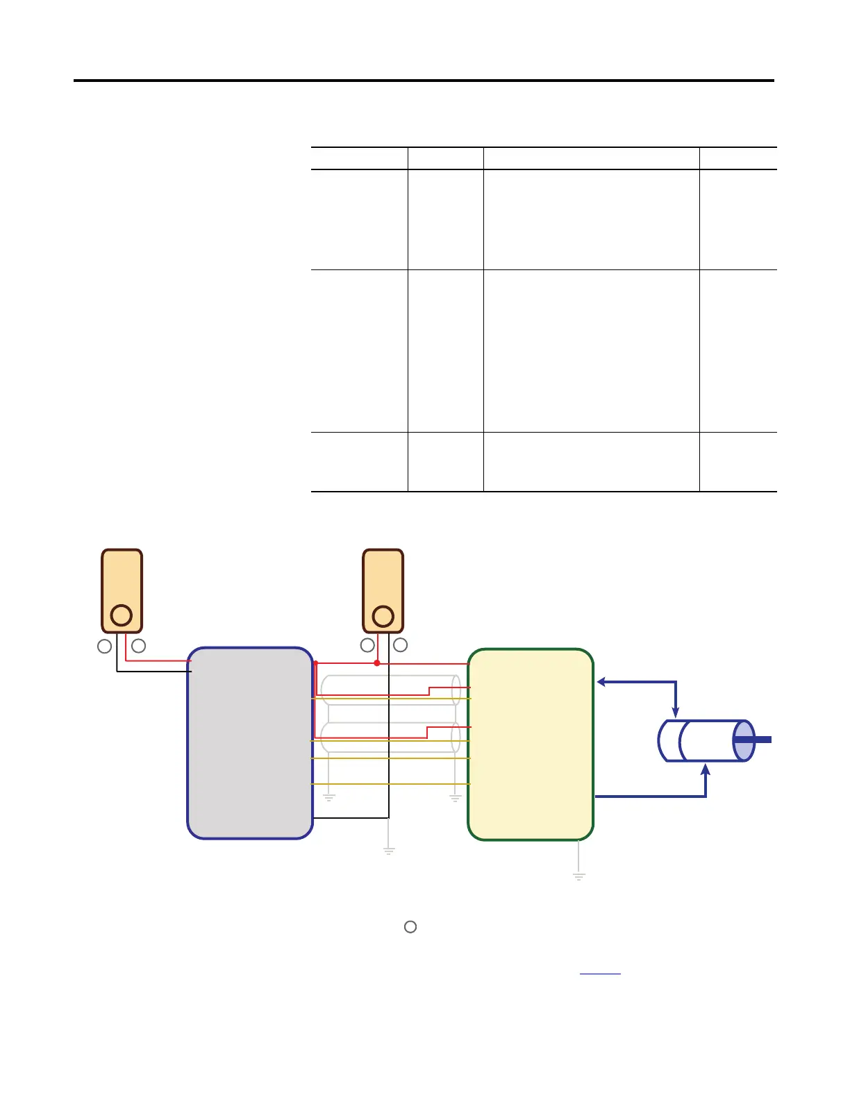
Motion Wiring Input/Output Description
Motion Signals Input/Output Description Uniqueness
2080-LC30-xxQVB
2080-LC50-xxQVB
Kinetix3
+DC 24
-DC 24
+CM0
+CM1
O-00
O-03
O-06
O-07
-CM0
-CM1
Pin 1, 2
Pin 49(CLK+)
Pin 12(CLK-)
Pin25(DIR+)
Pin 14(DIR-)
Pin 3(Enable)
Pin 7(RST)
1
2
24V
Power
Supply
–
_
Encoder
Motor
Encoder signal cable
Motor power cable
+
+
24V
Power
Supply
(2) To help you configure Kinetix3 drive parameters so the drive can communicate and be controlled by a
Micro830/Micro850/Micro870 controller, see publication CC-QS033
. The parameter Command Type
must be set to “Step/Direction.Positive Logic”, and the parameter Controller Output Type must be set
to “Open Collector Input”.
46056
Notes:
(1) Drive Enable (Pin 3) and Reset Drive (Pin 7) will be operating as sourcing inputs when (Pin1,2)
connected to – of the Power Supply 2.