Rockwell Automation Publication 2080-UM002K-EN-E - March 2019 3
Hardware Overview Chapter 1
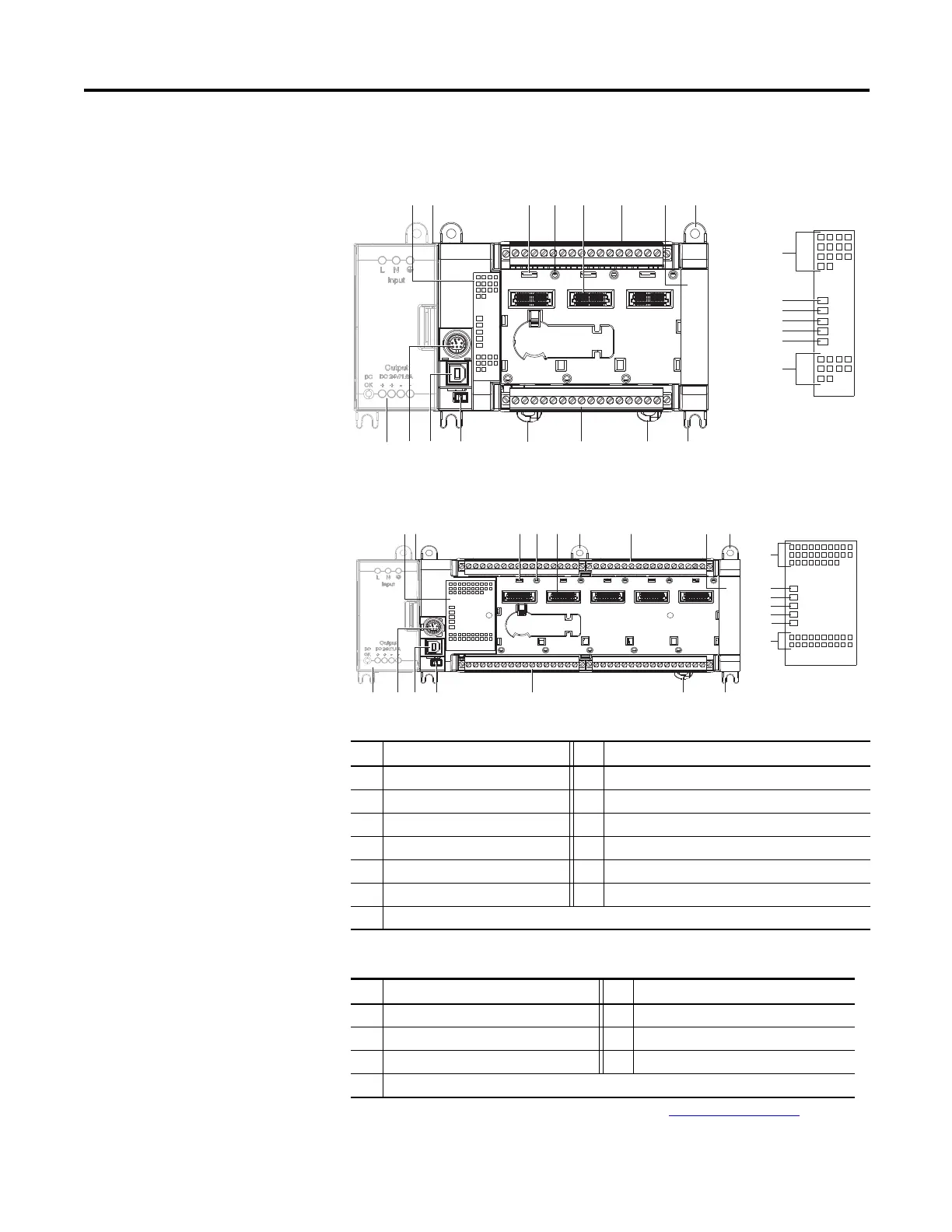
Controller Description
Description Description
1 Status indicators 8 Mounting screw hole / mounting foot
2 Optional power supply slot 9 DIN rail mounting latch
3 Plug-in latch 10 Mode switch
4 Plug-in screw hole 11 Type B connector USB port
5 40 pin high speed plug-in connector 12 RS-232/RS-485 non-isolated combo serial port
6 Removable I/O terminal block 13 Optional AC power supply
7 Right-side cover
Status Indicator Description
(1)
(1) For detailed description of the different status LED indicators, see Troubleshooting
on page 303.
Description Description
14 Input status 18 Force status
15 Power status 19 Serial communications status
16 Run status 20 Output status
17 Fault status
12 3 4 5 6 7 8
89910111213 6
45016
45017
Micro830 24-point controllers and status indicators
Controller
Status indicator
12
12
11
1013 6 9 8
34 5 6 7 88
45036
45037
Micro830 48-point controllers and status indicators
Status indicator
Controller