Rockwell Automation Publication 2080-UM002K-EN-E - March 2019 235
Specifications Appendix A
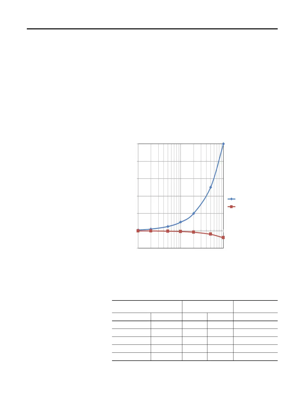
PTO Output Duty Cycle Error
Turn On/Off time for the Micro830, Micro850, and Micro870 controllers for
the PTO output port is 0.2 µs and 2.5 µs max, respectively. Duty cycle error is:
Positive error = 2.5 µs * F
Negative error = -0.2 µs * F
The plot below shows duty cycle error vs. frequency.
To get the duty cycle error at a certain frequency, for example, the user sets
frequency to 20 kHz, and sets duty cycle to 30% in Connected Components
Workbench software, then actual duty cycle is
PTO Typical Readings
Error (Percentage)
Frequency
0.25
0.2
0.15
0.1
0.05
0
-0.05
1000
10000
100000
Positive Error
Negative Error
PTO Typical Readings
Expected Duty Cycle Typical Duty Cycle
(1.27 KΩ load)
Frequency (kHz) %Duty Cycle Minimum Maximum %Duty Cycle
5 5% 4.90% 6.25% 5.48
5 10% 9.90% 11.25% 10.5
5 20% 19.90% 21.25% 20.5
5 40% 39.90% 41.25% 40.5
5 55% 54.90% 56.25% 55.5