Home
Allen-Bradley
Controller
Micro830
Allen-Bradley Micro830 User Manual
5
of 1
of 1 rating
354 pages
Give review
Manual
Specs
To Next Page
To Next Page
To Previous Page
To Previous Page
Loading...
Rockwell Automa
tion Publicatio
n 2080-UM0
02K-EN-E - Marc
h 2019
69
Communication Connections
Chapter
5
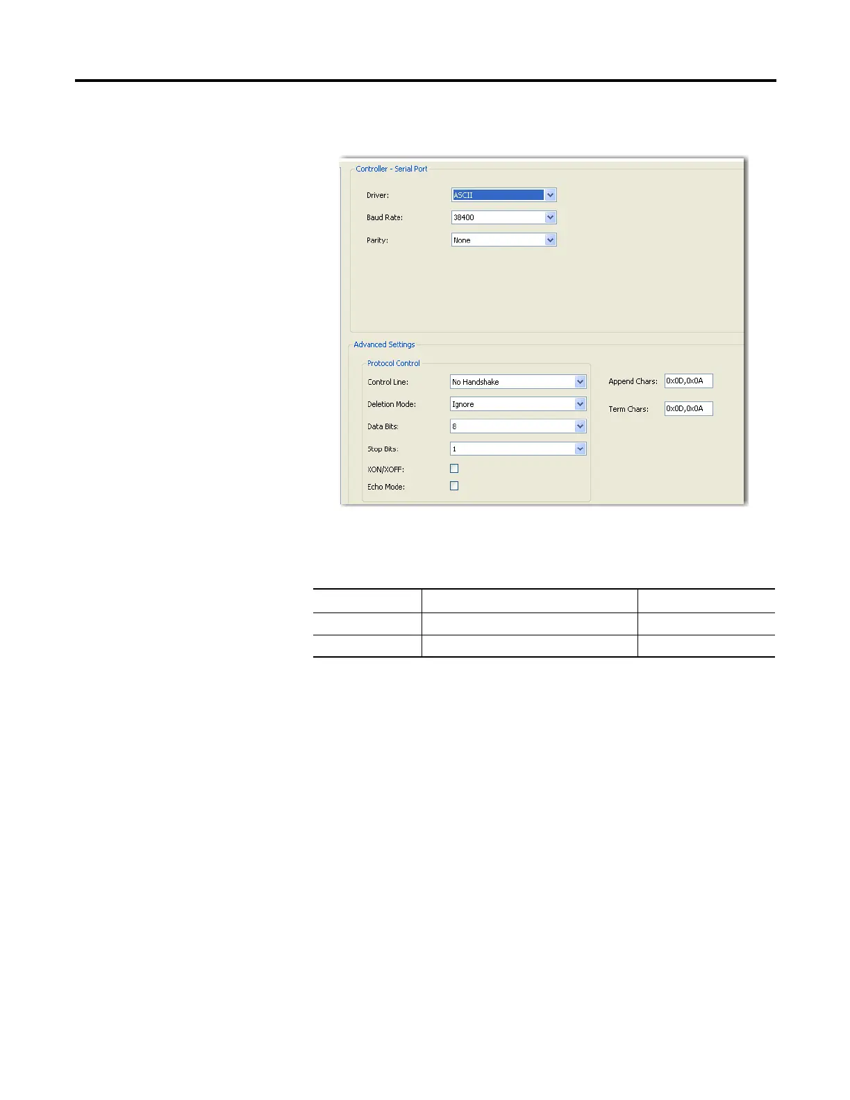
2.
Sele
ct AS
CII on the Dr
ive
r field.
3.
Spe
ci
f
y
b
aud
r
ate
an
d p
a
rit
y
.
ASCII Param
eters
Parameter
Options
Default
Baud Rate
1200, 2400, 4800, 9600,
19200, 38400
19200
Parity
None, Odd, Even
None
82
84
Table of Contents
Default Chapter
3
Additional Resources
3
Conformal Coated Catalogs
3
Preface
3
Purpose of this Manual
3
Who Should Use this Manual
3
Table of Contents
7
Chapter 1 Hardware Features
16
Hardware Overview
16
Micro830 Controllers
16
Micro850 Controllers
18
Micro870 Controllers
20
Embedded Ethernet Support
22
Embedded Serial Port Cables
22
Programming Cables
22
Chapter 2 Programming Software for Micro800 Controllers
25
Obtain Connected Components Workbench Software
25
Use Connected Components Workbench Software
25
Controller Changes in Run Mode
25
Using Run Mode Change (RMC)
26
About Your Controller
25
Uncommitted Changes
27
RMC Memory
28
Limitations of RMC
30
Using Run Mode Configuration Change (RMCC)
31
Using Modbus RTU Communication
32
Using Ethernet/Ip Communication
33
Agency Certifications
35
Compliance to European Union Directives
35
EMC Directive
36
Low Voltage Directive
36
Installation Considerations
36
Environment and Enclosure
38
Preventing Electrostatic Discharge
38
Safety Considerations
39
North American Hazardous Location Approval
39
Disconnecting Main Power
39
Safety Circuits
40
Power Distribution
40
Periodic Tests of Master Control Relay Circuit
40
Power Considerations
41
Isolation Transformers
41
Power Supply Inrush
41
Loss of Power Source
41
Input States on Power down
42
Other Types of Line Conditions
42
Preventing Excessive Heat
42
Master Control Relay
43
Using Emergency-Stop Switches
44
Schematic - Using IEC Symbols
45
Schematic - Using ANSI/CSA Symbols
46
Chapter 3 Controller Mounting Dimensions
47
Mounting Dimensions
47
DIN Rail Mounting
50
Panel Mounting
50
Panel Mounting Dimensions
51
System Assembly
53
Install Your Controller
47
Chapter 4
55
Wire Your Controller
55
Wiring Requirements and Recommendation
55
Use Surge Suppressors
56
Recommended Surge Suppressors
58
Grounding the Controller
59
Wiring Diagrams
60
Controller I/O Wiring
66
Minimize Electrical Noise
66
Analog Channel Wiring Guidelines
66
Minimize Electrical Noise on Analog Channels
66
Grounding Your Analog Cable
67
Wiring Examples
67
Embedded Serial Port Wiring
69
Chapter 5
71
Communication Connections
71
Overview
71
Supported Communication Protocols
71
Modbus RTU
73
CIP Serial Client/Server (RS-232 Only)
73
Ascii
73
Modbus TCP Client/Server
74
CIP Symbolic Client/Server
74
CIP Client Messaging
76
Sockets Client/Server TCP/UDP
76
CIP Communications Pass-Thru
76
Examples of Supported Architectures
76
Use Modems with Micro800 Controllers
78
Making a DF1 Point-To-Point Connection
78
Construct Your Own Modem Cable
78
Configure Serial Port
79
Configure CIP Serial Driver
79
Rockwell Automation Publication 2080-UM002K-EN-E - March
80
Configure Modbus RTU
81
Configure ASCII
82
Configure Ethernet Settings
84
Validate IP Address
86
Ethernet Host Name
86
Configure CIP Serial Driver
87
OPC Support Using Rslinx Enterprise
87
Chapter 6 Overview of Program Execution
89
Execution Rules
90
Program Execution in Micro800
89
Optional Module
90
Controller Load and Performance Considerations
91
Periodic Execution of Programs
91
Power up and First Scan
92
Variable Retention
92
Guidelines and Limitations for Advanced Users
93
Memory Allocation
93
Chapter 7 PTO Motion Control
95
Use the Micro800 Motion Control Feature
97
Motion Control
95
Input and Output Signals
98
Motion Control Function Blocks
101
General Rules for the Motion Control Function Blocks
103
Motion Axis and Parameters
111
Motion Axis State Diagram
112
Axis States
113
Limits
114
Motion Stop
116
Motion Direction
117
Axis Elements and Data Types
118
Axis Error Scenarios
119
Mc_Engine_Diag Data Type
120
Function Block and Axis Status Error Codes
120
Major Fault Handling
123
Motion Axis Configuration in Connected Components Workbench
123
Add New Axis
124
Edit Axis Configuration
125
Axis Start/Stop Velocity
132
Real Data Resolution
132
PTO Pulse Accuracy
134
Motion Axis Parameter Validation
135
Delete an Axis
135
Monitor an Axis
135
Homing Function Block
136
Conditions for Successful Homing
137
Mc_Home_Abs_Switch
137
Mc_Home_Limit_Switch
139
Mc_Home_Ref_With_Abs
140
Mc_Home_Ref_Pulse
142
Mc_Home_Direct
143
Use PTO for PWM Control
144
POU Pwm_Program
145
HSC Feedback Axis
146
Chapter 8
147
High-Speed Counter Overview
147
Programmable Limit Switch Overview
147
Use the High-Speed Counter and Programmable Limit Switch
147
What Is High-Speed Counter
148
Features and Operation
148
HSC Inputs and Wiring Mapping
149
High Speed Counter (HSC) Data Structures
153
HSC APP Data Structure
153
PLS Enable (Hscapp.plsenable)
153
Hscid (Hscapp.hscid)
154
HSC Mode (Hscapp.hscmode)
154
Accumulator (HSCAPP. Accumulator)
160
High Preset (Hscapp.hpsetting)
160
Low Preset (Hscapp.lpsetting)
161
Overflow Setting (Hscapp.ofsetting)
161
Underflow Setting (Hscapp.ufsetting)
161
Output Mask Bits (Hscapp.outputmask)
162
High Preset Output (Hscapp.hpoutput)
163
Low Preset Output (Hscapp.lpoutput)
163
HSC STS (HSC Status) Data Structure
164
Counting Enabled (Hscsts.countenable)
164
Error Detected (Hscsts.errordetected)
164
Count up (Hscsts.countupflag)
165
Count down (Hscsts.countdownflag)
165
Mode Done (Hscsts.mode1Done)
165
Overflow (HSCSTS.OVF)
165
Underflow (HSCSTS.UNF)
166
Count Direction (Hscsts.countdir)
166
High Preset Reached (Hscsts.hpreached)
166
Low Preset Reached (Hscsts.lpreached)
167
Overflow Interrupt (Hscsts.ofcauseinter)
167
Underflow Interrupt (Hscsts.ufcauseinter)
167
High Preset Interrupt (Hscsts.hpcauseinter)
168
Low Preset Interrupt (Hscsts.lpcauseinter)
168
Programmable Limit Switch Position (Hscsts.plsposition)
168
Error Code (Hscsts.errorcode)
169
Accumulator (Hscsts.accumulator)
169
High Preset (HSCSTS.HP)
169
Low Preset (HSCSTS.LP)
170
High Preset Output (Hscsts.hpoutput)
170
Low Preset Output (Hscsts.lpoutput)
170
HSC (High Speed Counter) Function Block
171
HSC Commands (Hsccmd)
171
HSC_SET_STS Function Block
173
Programmable Limit Switch (PLS) Function
173
PLS Data Structure
174
PLS Operation
174
PLS Example
175
HSC Interrupts
176
HSC Interrupt Configuration
177
HSC Interrupt POU
178
Auto Start (HSC0.AS)
178
Mask for IV (HSC0.MV)
178
Mask for in (HSC0.MN)
178
Mask for IH (HSC0.MH)
179
Mask for IL (HSC0.ML)
179
HSC Interrupt Status Information
179
User Interrupt Enable (Hsc0.Enabled)
179
User Interrupt Executing (HSC0.EX)
179
User Interrupt Pending (HSC0.PE)
180
User Interrupt Lost (HSC0.LS)
180
Use HSC
180
Chapter 9
181
Controller Security
181
Exclusive Access
181
Password Protection
181
Compatibility
182
Work with a Locked Controller
183
Upload from a Password-Protected Controller
183
Debug a Password-Protected Controller
183
Download to a Password-Protected Controller
183
Transfer Controller Program and Password-Protect Receiving
184
Controller
184
Back up and Restore a Password-Protected Controller
185
Configure Controller Password
185
Recover from a Lost Password
186
Using the Memory Module Plug-In
186
Chapter 10
191
Overview
191
Project Backup and Restore
192
Backup and Restore Directory Structure
193
Powerup Settings in Configmefirst.txt
194
General Configuration Rules in Configmefirst.txt
196
Configmefirst.txt Errors
197
Deliver Project Updates to Customers through Email
197
Data Log
200
Data Log Directory Structure
201
Data Log Function (DLG) Block
202
Recipe
205
Recipe Directory Structure
206
Recipe Function (RCP) Block
206
Quickstart Projects for Data Log and Recipe Function Blocks
209
Use the Data Log Feature
210
Use the Recipe Feature
216
Appendix A Micro830 Controllers
223
The Following Tables Provide Specifications, Ratings, and Certifications
223
For the Micro830 Controllers
223
Micro830 10-Point Controllers
223
Micro830 16-Point Controllers
226
Micro830 24-Point Controllers
228
Micro830 48-Point Controllers
231
Environmental Specifications
233
Certifications
234
Specifications
223
Micro850 Controllers
235
Micro850 24-Point Controllers
235
Micro850 48-Point Controllers
238
Environmental Specifications
241
Certifications
242
Micro870 Controllers
243
Micro870 24-Point Controllers
243
Environmental Specifications
246
Certifications
247
Relay Chart for Micro830, Micro850, and Micro870 Controllers
248
Micro800 Programmable Controller External AC Power Supply
253
Appendix B Modbus Mapping
255
Endian Configuration
255
Mapping Address Space and Supported Data Types
255
Example 1, Panelview Component HMI (Master) to Micro800
256
(Slave)
256
Example 2, Micro800 (Master) to Powerflex 4M Drive (Slave)
258
Performance
260
Modbus Mapping for Micro800
255
Establish Communications between Rslinx and a Micro830/Micro850
268
Micro870 Controller through USB
268
Configure Controller Password
275
Set Controller Password
275
Change Password
277
Clear Password
278
Use the High Speed Counter
278
Create the HSC Project and Variables
280
Assign Values to the HSC Variables
283
Assign Variables to the Function Block
286
Run the High Speed Counter
287
Use the Programmable Limit Switch (PLS) Function
289
Forcing I/Os
291
Checking if Forces (Locks) Are Enabled
291
I/O Forces after a Power Cycle
292
Using Run Mode Change
293
Create the Project
293
Edit the Project Using Run Mode Change
296
Appendix C Flash Upgrade Your Micro800 Firmware
261
Flash Upgrade from Microsd Card
264
Appendix D Information about Using Interrupts
301
What Is an Interrupt
301
When Can the Controller Operation be Interrupted
302
Priority of User Interrupts
302
User Interrupt Configuration
304
User Fault Routine
304
User Interrupts
301
User Interrupt Instructions
305
STIS - Selectable Timed Start
305
UID - User Interrupt Disable
306
UIE - User Interrupt Enable
308
UIF - User Interrupt Flush
309
UIC - User Interrupt Clear
310
Using the Selectable Timed Interrupt (STI) Function
311
Selectable Time Interrupt (STI) Function Configuration and Status
312
STI Function Configuration
312
STI Function Status Information
312
Event Input Interrupt (EII) Function Configuration and Status
314
EII Function Configuration
314
EII Function Status Information
315
Appendix E Status Indicators on the Controller
317
Using the Event Input Interrupt (EII) Function
314
Error Codes
319
Fault Types
319
Corrective Action for Recoverable and Non-Recoverable Faults
327
Normal Operation
319
Retrieve a Fault Log
327
Controller Error Recovery Model
328
Calling Rockwell Automation for Assistance
329
Appendix F
332
PID Function Block
332
IPIDCONTROLLER Function Block
335
How to Autotune
338
How Autotune Works
339
PID Application Example
340
PID Code Sample
342
Appendix G
345
Troubleshooting an Autotune Process
340
Calculate Total Power for Your Micro830/Micro850/Micro870
345
Controller
345
Rockwell Automation Publication 2080-UM002K-EN-E - March
346
Index
347
Index
348
Index
349
Index
350
Index
351
Index
352
Other manuals for Allen-Bradley Micro830
User Manual
284 pages
5
Based on 1 rating
Ask a question
Give review
Questions and Answers:
Need help?
Do you have a question about the Allen-Bradley Micro830 and is the answer not in the manual?
Ask a question
Allen-Bradley Micro830 Specifications
General
Brand
Allen-Bradley
Model
Micro830
Category
Controller
Language
English
Related product manuals
Allen-Bradley Micro800
78 pages
Allen-Bradley Micro820
184 pages
Allen-Bradley Micro850
24 pages
Allen-Bradley Micro810
102 pages
Allen-Bradley Micro870
354 pages
Allen-Bradley MicroLogix 1100
256 pages
Allen-Bradley micrologix 1500
174 pages
Allen-Bradley MicroLogix 1400
694 pages
Allen-Bradley MicroLogix 1000
422 pages
MicroLogix 1000 PLC
2 pages
Allen-Bradley 1756-M08SE
236 pages
Allen-Bradley PowerFlex 525
244 pages