Connecting the System
3–11
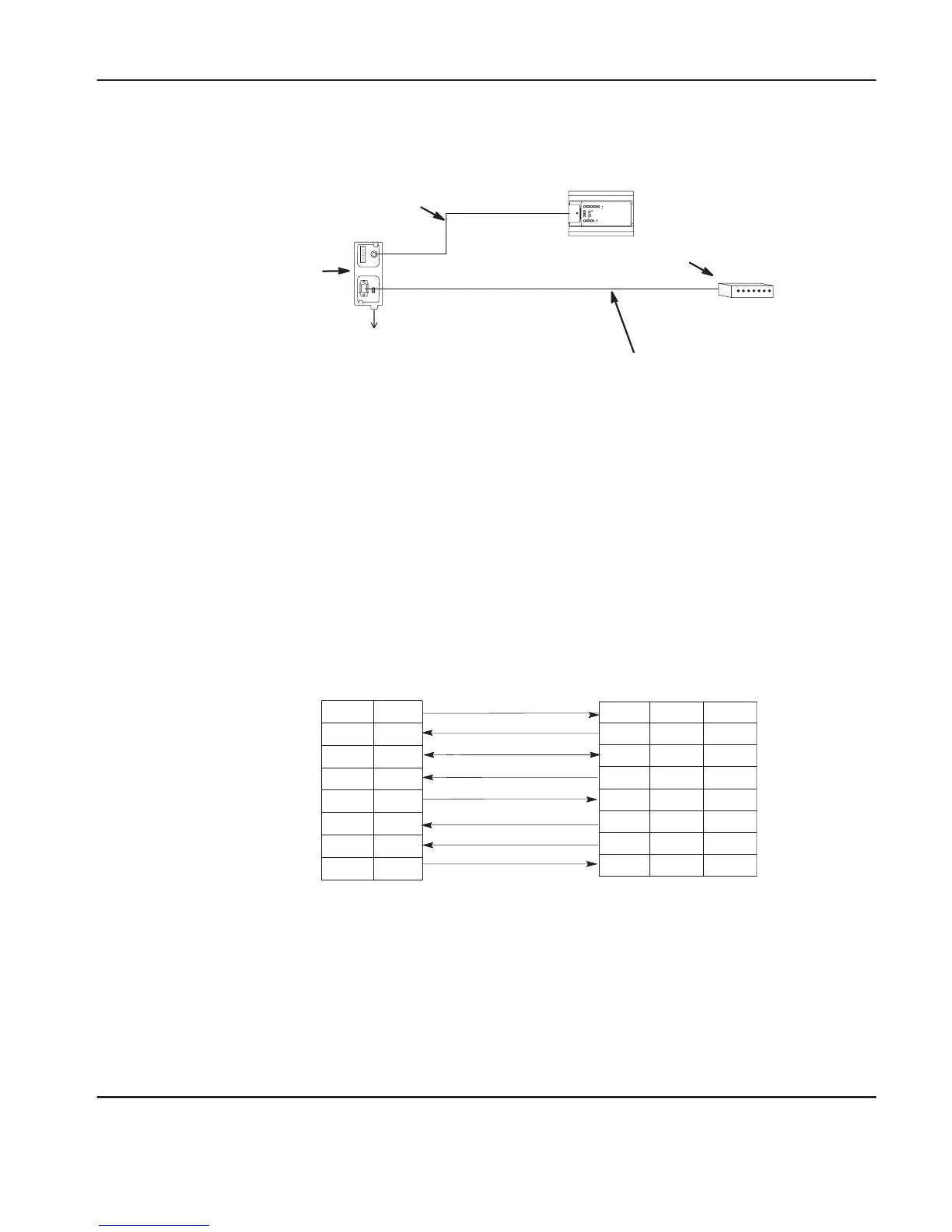
DF1 Isolated Modem Connection
24V
dc
(Not needed in this configuration
since the MicroLogix 1000 provides
power to the AIC+ via port 2.)
User supplied modem cable
MicroLogix 1000
Modem
1761-CBL-AM00
or
1761-CBL-HM02
Selection Switch Up
AIC+
(1761-NET-AIC)
For additional information on connections using the AIC+, see the Advanced
Interface Converter (AIC+) and DeviceNet Interface (DNI) Installation Instructions,
Publication 1761-5.11.
Constructing
Y
our Own Modem Cable
If you construct your own modem cable, the maximum cable length is 15.24 m (50
ft) with a 25-pin or 9-pin connector. Refer to the following typical pinout:
25-Pin
9-Pin
2
5
1
4
6
8
7
3
RTS
TXD
RXD
GND
CD
DTR
DSR
CTS
RXD
3
7
8
20
6
5
4
GND
CD
DTR
DSR
CTS
RTS
TXD
2
Modem
Optical Isolator
2
5
1
4
6
8
7
3
9-Pin
AIC+
efesotomasyon.com - Allen Bradley,Rockwell,plc,servo,drive

 Loading...


