Publication 1762-RM001C-EN-P
Sequencer Instructions 15-9
On a false-to-true rung transition, the SQL instruction loads words or long
words into a sequencer file at each step of a sequencer operation. This
instruction uses the following operands:
•
File - This is the sequencer reference file. Its contents are received on
an element-by-element basis from the source.
•
Source - The source operand is a constant or address of the value
used to fill the currently available position sequencer file. The address
level of the source must match the sequencer file. If file is a word
type, then source must be a word type. If file is a long word type,
then source must be a long word type. The data range for the source
is from -32768 to 32767 (word) or -2,147,483,648 to 2,147,483,647
(long word).
•
Control - This is a control file address. The status bits, stack length,
and the position value are stored in this element. The control element
consists of 3 words:
•
Length - The length operand contains the number of steps in the
sequencer file (this is also the length of source if it is a file data type).
The length of the sequencer can range from 1 to 256.
•
Position - This is the current location or step in the sequencer file (as
well as source if it is a file data type). It determines the next location
in the stack to receive the value or constant found in source. Position
is a component of the control register. The position can range from 0
to 255.
NOTE
If file type is word, then mask and source must be
words. If file type is long word, mask and source
must be long words.
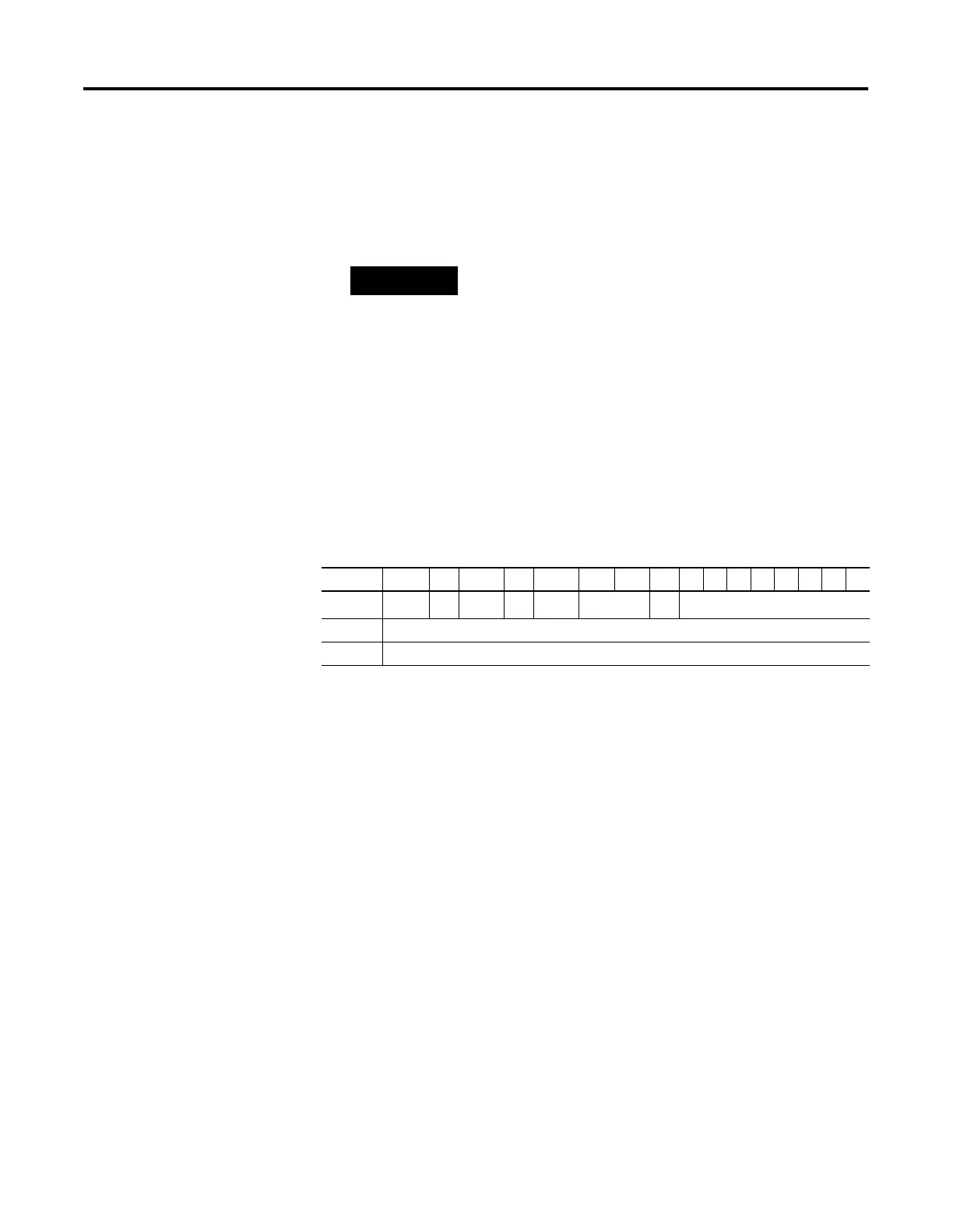
15 14 13 12 11 10 9 8 7 6 5 4 3 2 1 0
Word 0
EN
(1)
(1) EN - Enable Bit is set by a false-to-true rung transition and indicates that the instruction is enabled.
--
DN
(2)
(2) DN - Done Bit is set after the instruction has operated on the last word in the sequencer file. It is reset on the next
false-to-true rung transition after the rung goes false.
--
ER
(3)
(3) ER - Error Bit is set when the controller detects a negative position value, or a negative or zero length value. When the
ER bit is set, the minor error bit (S2:5/2) is also set.
not used FD not used
Word 1 Length - contains the index of the last element in the sequencer reference file
Word 2 Position - the current position in the sequence

 Loading...


