Publication 1762-RM001C-EN-P
20-14 ASCII Instructions
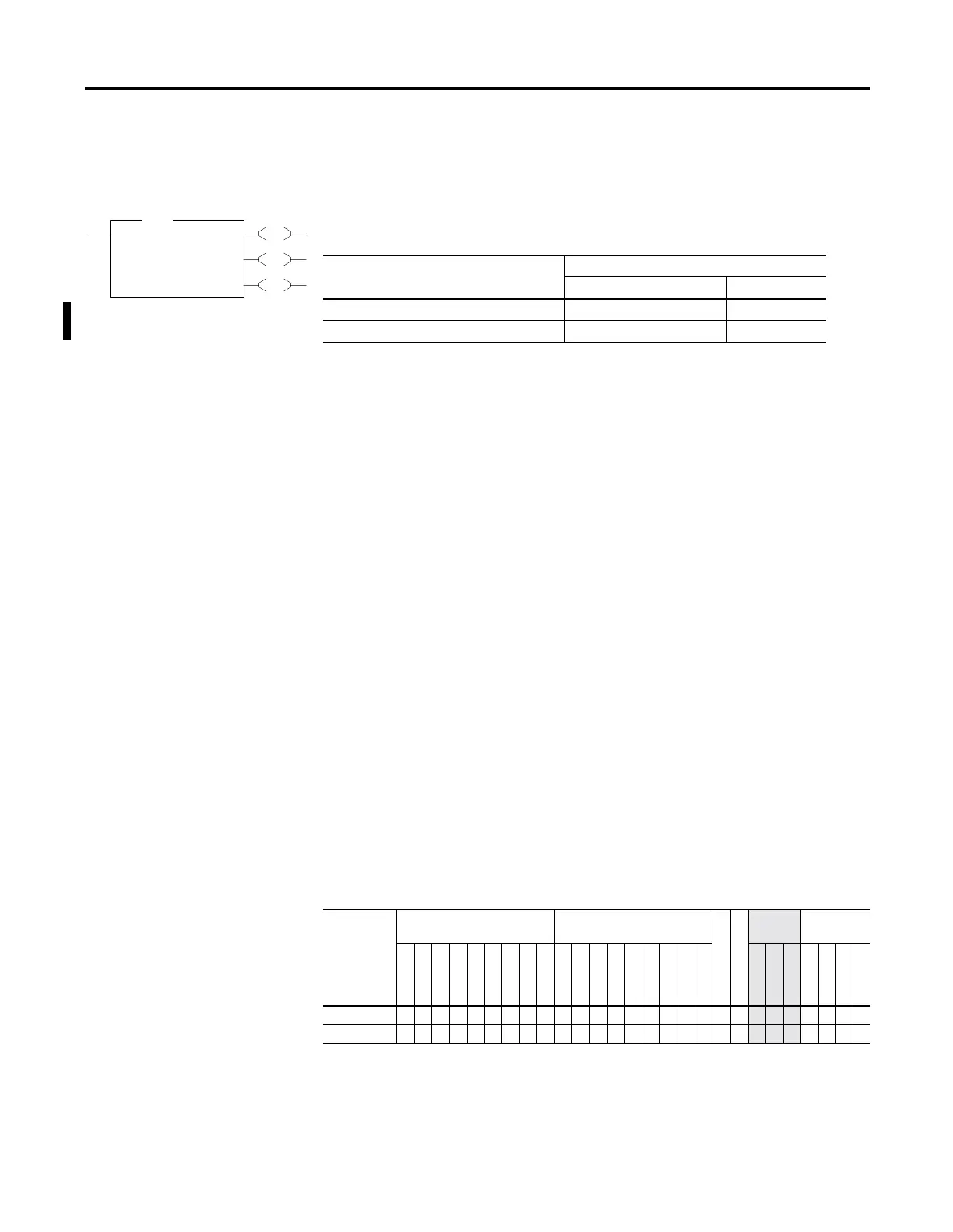
ABL - Test Buffer for Line
Instruction Type: output
The ABL instruction is used to determine the number of characters in the
receive buffer of the specified communication channel, up to and
including the end-of-line characters (termination). This instruction looks
for the two termination characters that you configure via the channel
configuration screen. On a false-to-true transition, the controller reports
the number of characters in the POS field of the control data file. The
channel configuration must be set to ASCII.
Entering Parameters
Enter the following parameters when programming this instruction:
•
Channel is the number of the RS-232 port, Channel 0. (For the
1764-LRP only, you can select either Channel 0 or Channel 1).
•
Control is the control data file. See page 20-6.
•
Characters are the number of characters in the buffer that the
controller finds (0 to 1024). This parameter is read-only and resides in
word 2 of the control data file.
•
Error displays the hexadecimal error code that indicates why the ER
bit was set in the control data file. See page 20-30 for error code
descriptions.
Addressing Modes and File Types can be used as shown below:
EN
DN
ER
ABL
Ascii Test For Line
Channel 0
Control R6:0
Characters 1<
Error 0<
ABL
Table 20.11 Execution Time for the ABL Instruction
Controller When Instruction Is:
True False
MicroLogix 1200 Series B, FRN 3 or later 115
µ
s + 8.6
µ
s/character 12.5
µ
s
MicroLogix 1500 Series B, FRN 4 or later 94
µ
s + 7.6
µ
s/character 11.4
µ
s
Table 20.12 ABL Instruction Valid Addressing Modes and File Types
For definitions of the terms used in this table see Using the Instruction Descriptions on page4-2.
Parameter
Data Files
(1)
(1) The Control data file is the only valid file type for the Control Element.
Function Files
CS - Comms
IOS - I/O
Address
Mode
Address
Level
O
I
S
B
T, C, R
N
ST
L
MG, PD
RTC
HSC
PTO, PWM
STI
EII
BHI
MMI
DAT
TPI
Immediate
Direct
Indirect
Bit
Word
Long Word
Element
Channel • •
Control •
• •

 Loading...


