Publication 1762-RM001C-EN-P
3-6 Function Files
Memory Module
Information Function
File
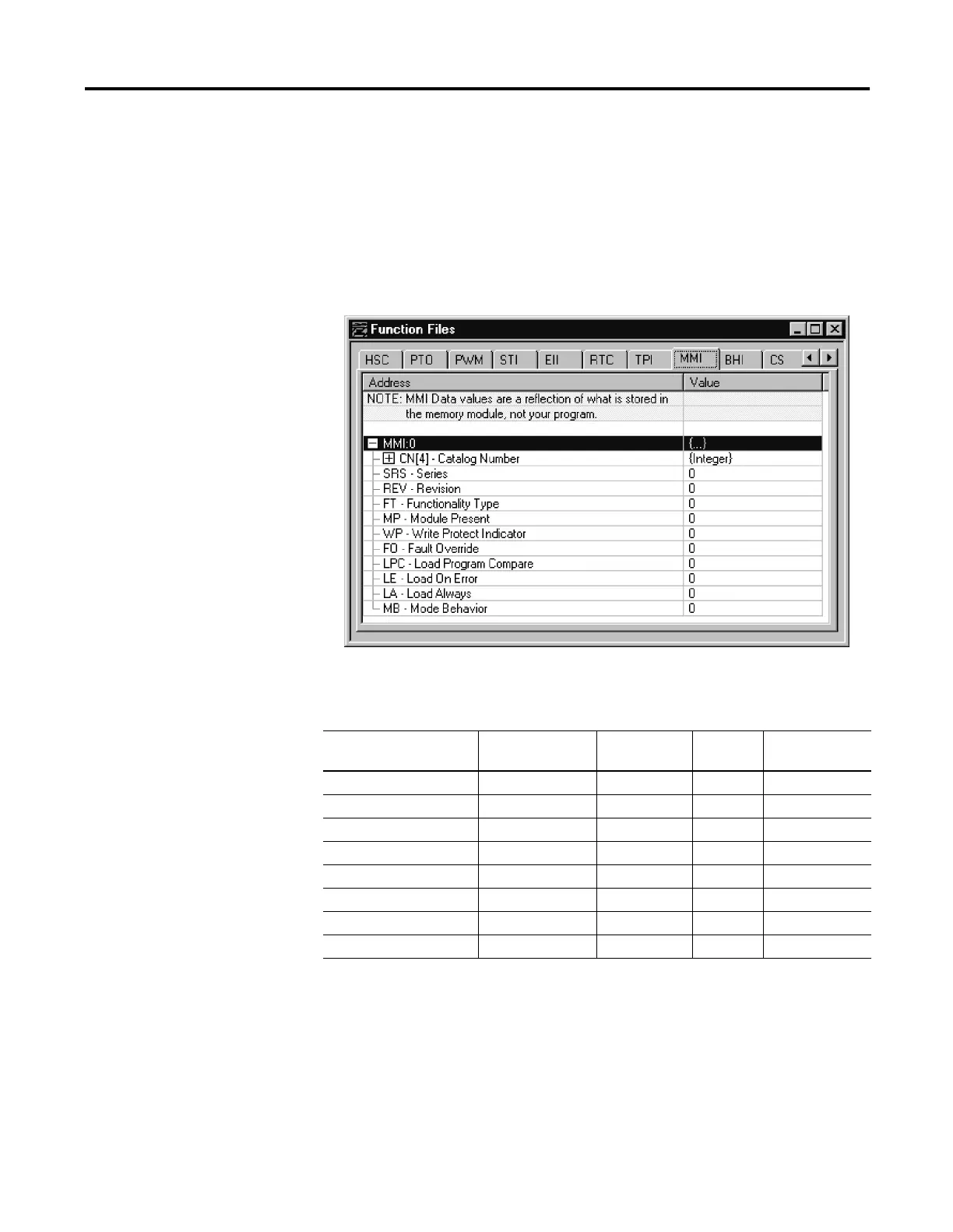
The controller has a Memory Module Information (MMI) File which is
updated with data from the attached memory module. At power-up or on
detection of a memory module being inserted, the catalog number, series,
revision, and type (memory module and/or real-time clock) are identified
and written to the MMI file in the user program. If a memory module and/
or real-time clock is not attached, zeros are written to the MMI file.
The memory module function file programming screen is shown below:
The parameters and their valid ranges are shown in the table below.
FT - Functionality Type
The LSB of this word identifies the type of module installed:
•
1 = Memory Module
•
2 = Real-Time Clock Module
•
3 = Memory and Real-Time Clock Module
Table 3.7 MMI Function File Parameters
Feature Address Data Format Type User Program
Access
FT - Functionality Type MMI:0.FT word (INT) status read-only
MP - Module Present MMI:0/MP binary (bit) status read-only
WP - Write Protect MMI:0/WP binary (bit) control read-only
FO - Fault Override MMI:0/FO binary (bit) control read-only
LPC - Program Compare MMI:0/LPC binary (bit) control read-only
LE - Load On Error MMI:0/LE binary (bit) control read-only
LA - Load Always MMI:0/LA binary (bit) control read-only
MB - Mode Behavior MMI:0/MB binary (bit) control read-only

 Loading...


