Publication 1762-RM001C-EN-P
1-10 I/O Configuration
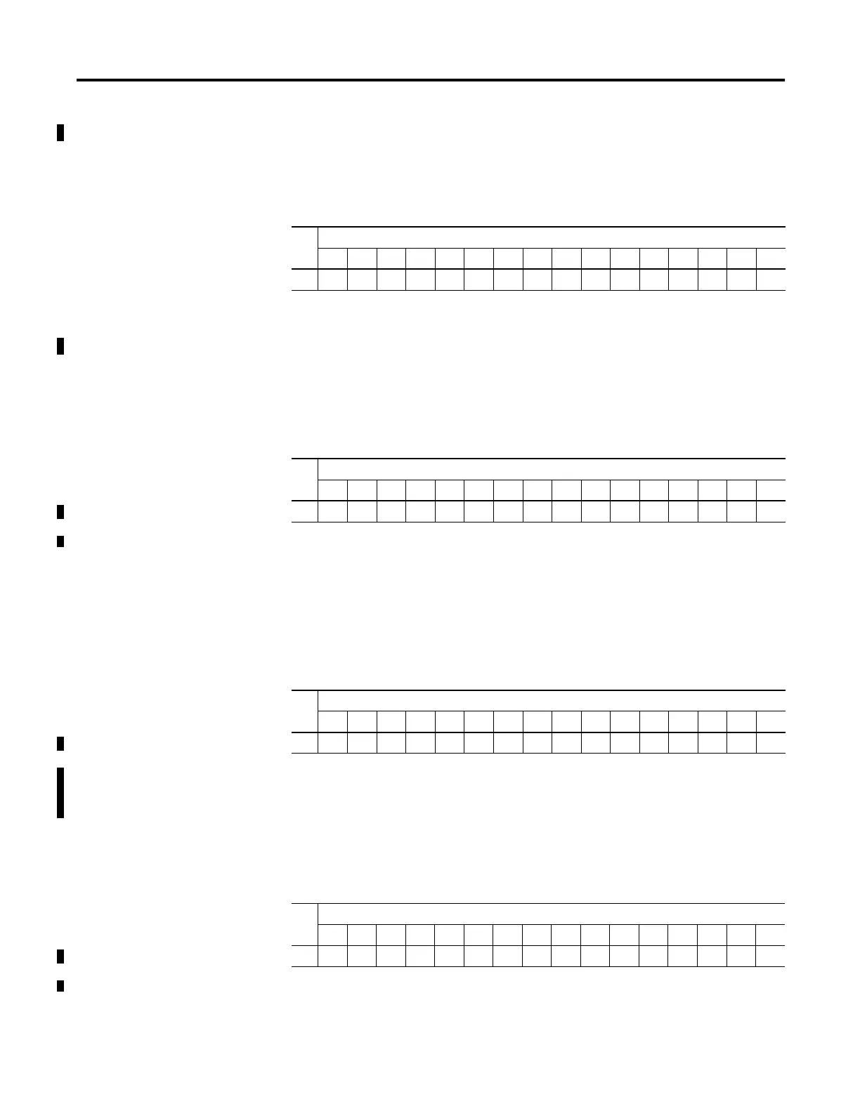
1769-IQ6XOW4 Input Image
For each module, the input data file contains the current state of the field
input points. Bit positions 0 through 5 correspond to input terminals 0
through 5, bits 6 through 15 are not used.
r = read, x = not used, always at a 0 or OFF state
1769-IQ6XOW4 Output Image
For each module, the output data file contains the current state of the
control program’s directed state of the discrete output points. Bit positions
0 through 3 correspond to output terminals 0 through 3, bits 4 through 15
are not used.
r/w = read and write, x = not used, always at a 0 or OFF state
1769-OA8, 1769-OW8, and 1769-OW8I Output Image
For each module, the output data file contains the current state of the
control program’s directed state of the discrete output points. Bit positions
0 through 7 correspond to output terminals 0 through 7, bits 8 through 15
are not used.
r/w = read and write, x = not used, always at a 0 or OFF state
1769-OB16, 1769-OB16P and 1769-OV16 Output Image
For each module, the output data file contains the current state of the
control program’s directed state of the discrete output points. Bit positions
0 through 15 correspond to output terminals 0 through 15.
r/w = read and write
Word
Input Bit Position
1514131211109876543210
0xxxxxxxxxxrrrrrr
Word
Output Bit Position
1514131211109876543210
0xxxxxxxxxxxxr/wr/wr/wr/w
Word
Output Bit Position
1514131211109876543210
0xxxxxxxxr/wr/wr/wr/wr/wr/wr/wr/w
Word
Output Bit Position
15 14 13 12 11 10 9 8 7 6 5 4 3 2 1 0
0 r/w r/w r/w r/w r/w r/w r/w r/w r/w r/w r/w r/w r/w r/w r/w r/w

 Loading...


