Publication 1762-RM001C-EN-P
22-12 Data Logging (MicroLogix 1500 1764-LRP Processor only)
Information for Creating Your Own Application
Controller Receives Communications Packet
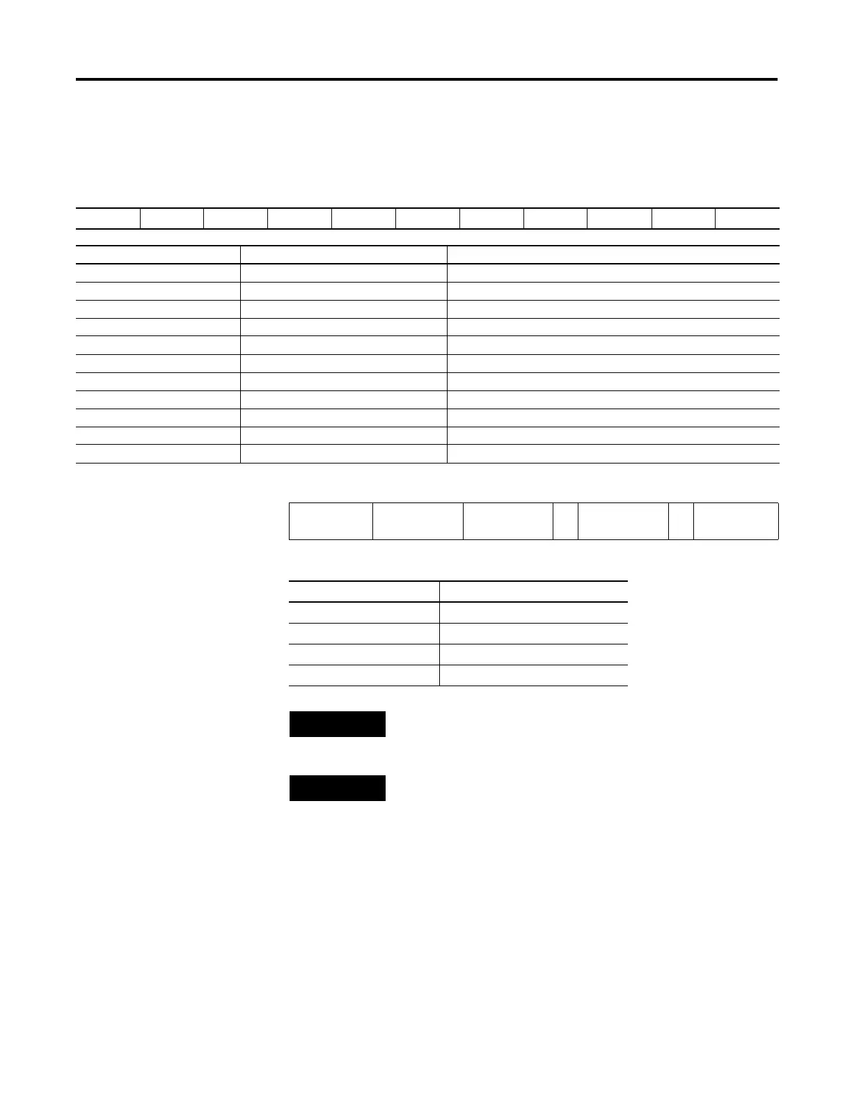
Table 22.5 Command Structure
DST SRC CMD 0f STS TNS FNC A2 Byte Size File No. File Tpe Ele. No. S/Ele. No.
Field Function Description
DST Destination Node
SRC Source Node
CMD Command Code
STS Status Code Set to zero (0)
TNS Transaction Number Always 2 bytes
FNC Function Code
Byte Size Number of bytes to be read Formatted string length (see equation below)
File Number Always set to zero (0)
File Type Must be A5 (hex)
Element Number Queue number Determines the queue to be read (0 to 255)
Sub/Element Number Always set to zero (0)
Table 22.6 Equation
Record Field 1 + Record Field 2 + Record Field 3 … + Record Field 7 = Formatted
String Length
Table 22.7 Record Field Sizes
Data Type Maximum Size
Word 7 bytes (characters)
Long Word 12 bytes (characters)
Date Field 11 bytes (characters)
Time Field 9 bytes (characters)
NOTE
The formatted string length cannot exceed 80 bytes in
length.
NOTE
The last byte will be a zero value representing the
terminator character.

 Loading...


