Publication 1762-RM001C-EN-P
Using the High-Speed Counter 5-21
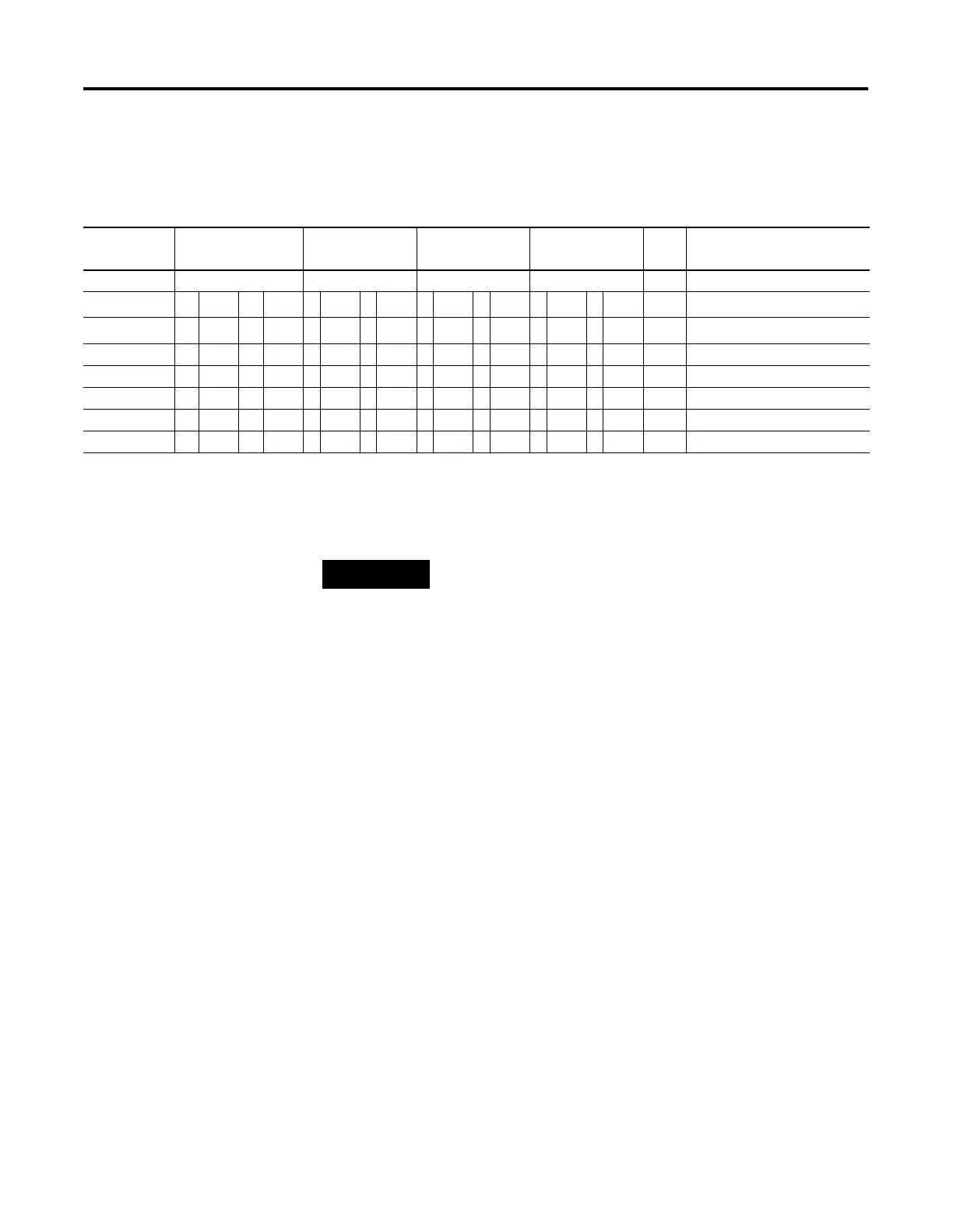
HSC Mode 7 - Quadrature Counter (phased inputs A and B) With External Reset
and Hold
Blank cells = don’t care, ⇑ = rising edge, ⇓ = falling edge
Table 5.11 HSC Mode 7 Examples
(1)
Input
Terminals
I1:0.0/0 (HSC0)
I1:0.0/4 (HSC1)
I1:0.0/1 (HSC0)
I1:0.0/5 (HSC1)
I1:0.0/2 (HSC0)
I1:0.0/6 (HSC1)
I1:0.0/3 (HSC0)
I1:0.0/7 (HSC1)
CE
Bit
Comments
Function Count A Count B Z reset Hold
Example 1
(2)
⇑
off (0) off (0) on (1) HSC Accumulator + 1 count
Example 2
(3)
⇓
off (0) off (0) off (0) on (1) HSC Accumulator - 1 count
Example3
⇓
off (0) off (0) on (1) Reset accumulator to zero
Example 4 on (1) Hold accumulator value
Example 5 on (1) Hold accumulator value
Example 6 off (0) on (1) Hold accumulator value
Example 7 off (0) off (0) Hold accumulator value
(1) HSC1 only applies to the MicroLogix 1500.
(2) Count input A leads count input B.
(3) Count input B leads count input A.
NOTE
Inputs I1:0.0/0 through I1:0.0/7 are available for use as
inputs to other functions regardless of the HSC being
used.

 Loading...


