14 POINT I/O 2 and 4 Relay Output Modules
Publication 1734-IN055H-EN-E - August 2016
Remove a Mounting Base
To remove a mounting base, you must remove any installed module, and the module
installed in the base to the right. Remove the Removable Terminal Block, if wired.
1. Unlatch the RTB handle on the I/O module.
2. Pull on the RTB handle to remove the Removable Terminal Block.
3. Press on the module lock on the top of the module.
4. Pull on the I/O module to remove from the base.
5. Repeat steps 1, 2, 3 and 4 for the module to the right.
6. Use a small bladed screwdriver to rotate the orange base locking screw to a
vertical position. This releases the locking mechanism.
7. Lift straight up to remove.
Communicate with Your Module
I/O messages are sent to (consumed) and received from (produced) the POINT I/O
modules. These messages are mapped onto the processor’s memory.
This POINT I/O output module does not produce input data (scanner Rx). It consumes
1 Byte of I/O data (scanner Tx).
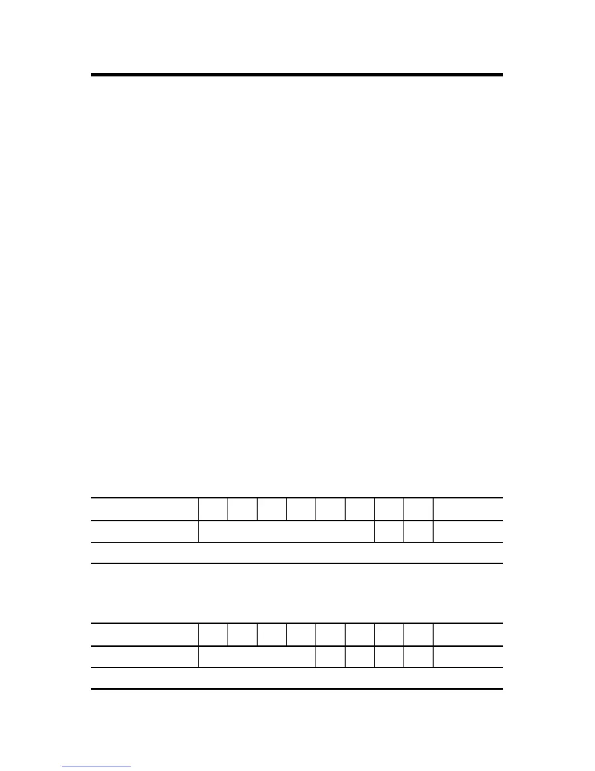
Default Data Map for 1734-OW2
Message size: 1 Byte
76543210
Consumes (scanner Tx) Not used Ch1 Ch0 Channel state
Where: 0 = Off, 1 = On
Default Data Map for 1734-OW4
Message size: 1 Byte
76543210
Consumes (scanner Tx) Not used Ch3 Ch2 Ch1 Ch0 Channel state
Where: 0 = Off, 1 = On
 Loading...