Rockwell Automation Publication 750-PM001N-EN-P - February 2017 285
Embedded Feature and Option Module Parameters Chapter 5
Universal Feedback
Registration
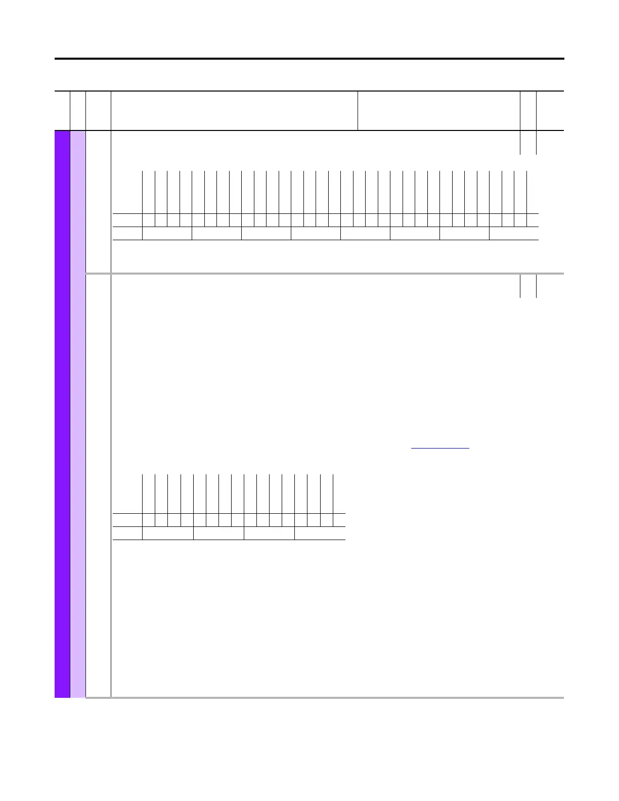
94 Rgsn Sts
Registration Status
RO 16-bit
Integer
Status of the configured registration events.
100
103
106
109
112
115
118
121
124
127
Rgsn Latch1 Cfg
Rgsn Latch2 Cfg
RO 16-bit
Integer
Rgsn Latch3 Cfg
Rgsn Latch4 Cfg
Rgsn Latch5 Cfg
Rgsn Latch6 Cfg
Rgsn Latch7 Cfg
Rgsn Latch8 Cfg
Rgsn Latch9 Cfg
Rgsn Latch10 Cfg
Registration Latch n Configure
Configures Registration Latch n.
The registration function consists of 10 sets of latches. The latched data includes a feedback position and associated time parameter. Time is relative to when the
feedback devices were last sampled. Once the registration function has been armed, the values for these parameters are captured (latched) upon the occurrence of
a trigger event. See functionality tables on following page.
The registration trigger for each latch is separately configured by its Latch Configuration Parameter. Refer to Figure 2 on page 287
. The trigger logic includes two
separate trigger stages. Each trigger stage is separately configured to use one of three possible registration input signals or the marker (Z pulse) of the selected
feedback channel. Trigger combination logic determines how the two stages are combined to define the trigger event conditions.
Bit 0 “Channel Sel” – Channel select (FB0 or FB1).
Bit 1 “Fwd Capture” – Direction select forward.
Bit 2 “Rev Capture” – Direction select reverse.
Bit 3 “Stg1 In b0” – Latch stage 1 input selection b0
Bit 4 “Stg1 In b1” – Latch stage 1 input selection b1
Bit 6 “Stg1EdgeRise” – Latch stage 1 edge/level select: Rising edge or high level
Bit 7 “Stg1EdgeFall” – Latch stage 1 edge/level select: Falling edge or low level
Bit 8 “Logic Sel b0” – Trigger stage combination logic
Bit 9 “Logic Sel b1” – Trigger stage combination logic
Bit 10 “Stg2 In b0” – Latch stage 2 input selection b0
Bit 11 “Stg2 In b1” – Latch stage 2 input selection b1
Bit 13 “Stg2EdgeRise” – Latch stage 2 edge/level select: Rising edge or high level
Bit 14 “Stg2EdgeFall” – Latch stage 2 edge/level select: Falling edge or low level
File
Group
No. Display Name
Full Name
Description
Values
Read-Write
Data Type
Options
Home Input
Rgsn Input 1
Rgsn Input 0
Reserved
Reserved
Reserved
Reserved
Reserved
Reserved
Reserved
Reserved
Reserved
Latch10Found
Latch10Armed
Latch9 Found
Latch9 Armed
Latch8 Found
Latch8 Armed
Latch7 Found
Latch7 Armed
Latch6 Found
Latch6 Armed
Latch5 Found
Latch5 Armed
Latch4 Found
Latch4 Armed
Latch3 Found
Latch3 Armed
Latch2 Found
Latch2 Armed
Latch1 Found
Latch1 Armed
Default00000000000000000000000000000000
Bit 313029282726252423222120191817161514131211109876543210
0 = False
1 = True
Options
Reserved
Stg2EdgeFall
Stg2EdgeRise
Reserved
Stg2 In b1
Stg2 In b0
Logic Sel b1
Logic Sel b0
Stg1EdgeFall
Stg1EdgeRise
Reserved
Stg1 In b1
Stg1 In b0
Rev Capture
Fwd Capture
Channel Sel
Default0000000000000000
Bit 1514131211109876543210
0 = Condition False
1 = Condition True
 Loading...


