Rockwell Automation Publication 750-PM001N-EN-P - February 2017 477
Application Notes Appendix C
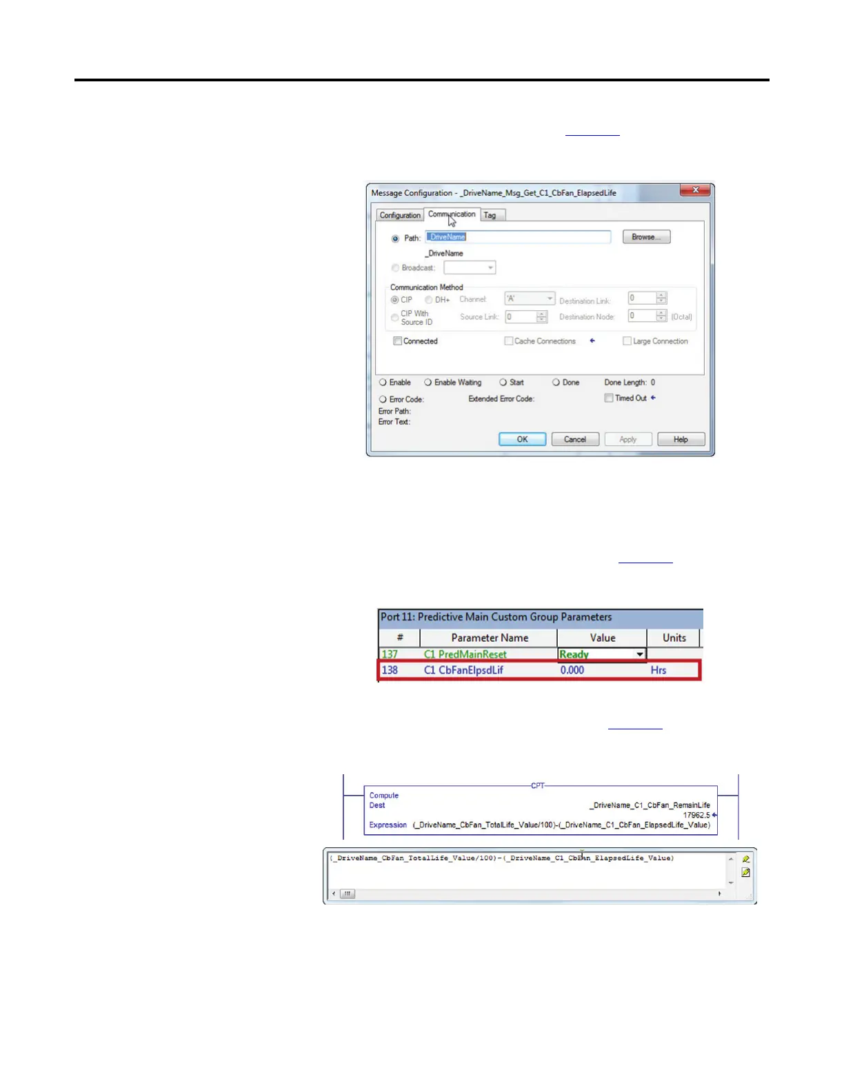
g. Click the Communication tab. See Figure 89.
Figure 89 - Message Configuration Screen - Communication Tab
h. In the Path field, enter the drive name to configure the communication
path of the message instruction to that drive.
In this case, the drive name in the Logix I/O tree is “_DriveName.”
i. The [Elapsed Life] data returns with a floating point (Real) data
format. The raw data is already in hours. See Figure 90
.
Figure 90 - Predictive Main Group Parameters (Port 11)
6. To calculate the [Remaining Life] parameter, use a Compute (CPT)
instruction with a subtraction expression. See Figure 91
.
Figure 91 - Compute (CPT) Instructions
 Loading...


