216 Rockwell Automation Publication 520-UM001G-EN-E - September 2014
Appendix F PID Set Up
• The Desired System Pressure set point is maintained as valves in the system
are opened and closed causing changes in flow.
• When the PID Control Loop is disabled, the Commanded Speed is the
Ramped Speed Reference.
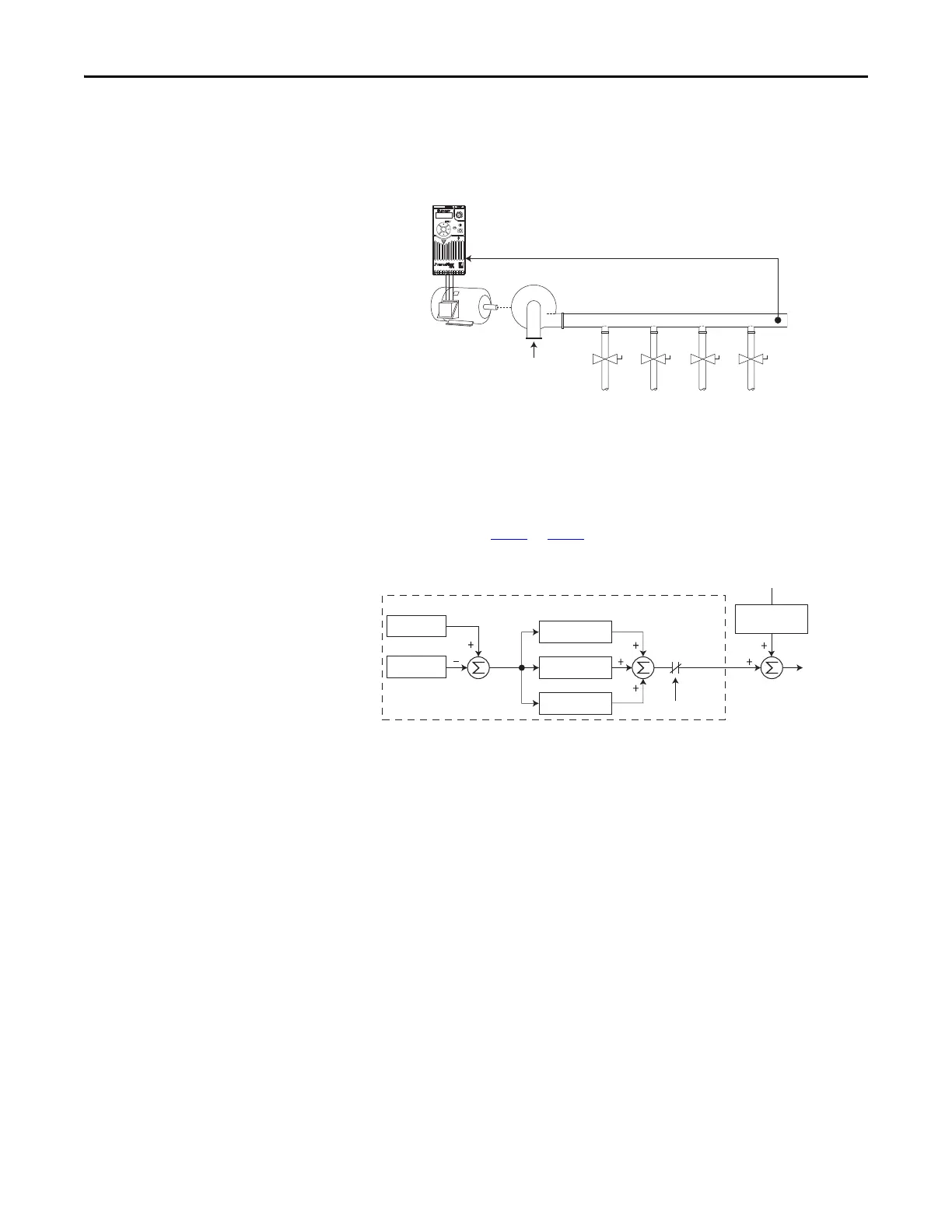
Trim Control
In Trim Control, the PID Output is added to the Speed Reference. In Trim
mode, the output of the PID loop bypasses the accel/decel ramp as shown. Trim
Control is used when A458
or A470 [PID x Trim Sel] is set to any option other
than 0.
Example
• In a winder application, the PID Reference equals the Equilibrium set
point.
• The Dancer Pot signal provides PID Feedback to the drive. Fluctuations in
tension result in a PID Error value.
• The Master Speed Reference sets the wind/unwind speed.
Pump
PID Feedback =
Pressure Transducer Signal
PID Reference =
Desired System Pressure
Esc
Sel
PID Prop Gain
PID Loop
PID Integ Time
PID Di Rate
PID Selected
[Speed Referencex]
PID Fdbk
PID Ref
PID
Error
PID
Output
Output
Freq
Accel/Decel
Ramp

 Loading...


