42 Rockwell Automation Publication 520-UM001G-EN-E - September 2014
Chapter 1 Installation/Wiring
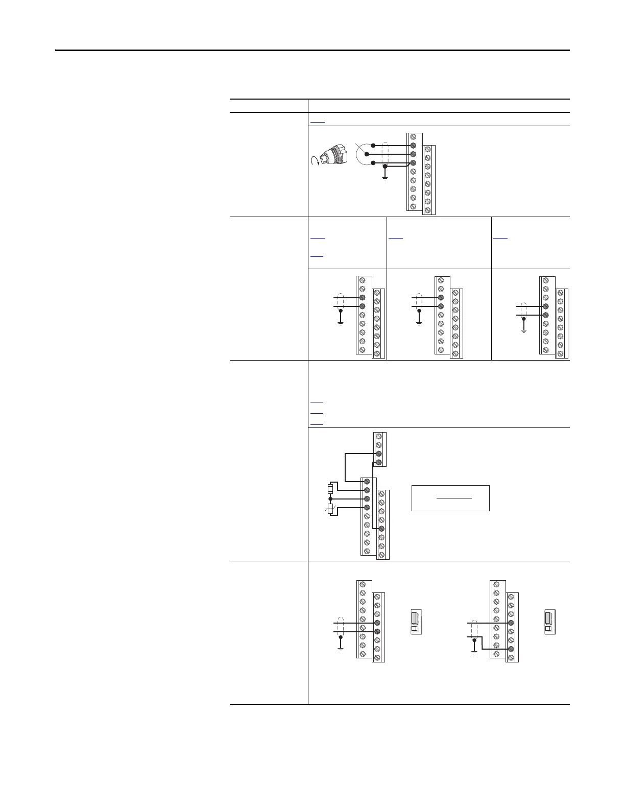
I/O Wiring Examples
I/O Connection Example
Potentiometer
1...10k Ω Pot.
Recommended
(2 W minimum)
P047
[Speed Reference1] = 5 “0-10V Input”
Analog Input
0-10V, 100k Ω impedance
4-20 mA, 250 Ω
impedance
Bipolar
P047 [Speed Reference1]
= 5 “0-10V Input” and
t093
[10V Bipolar Enbl]
= 1 “Bi-Polar In”
Unipolar (Voltage)
P047
[Speed Reference1]
= 5 “0-10V Input”
Unipolar (Current)
P047 [Speed Reference1]
= 6 “4-20mA Input”
Analog Input, PTC
For Drive Fault
Wire the PTC and External Resistor (typically matched to the PTC Hot Resistance) to I/O
Terminals 12, 13, 14.
Wire R2/R3 Relay Output (SRC) to I/O Terminals 5 & 11.
t065 [DigIn TermBlk 05] = 12 “Aux Fault”
t081 [Relay Out 2 Sel] = 10 “Above Anlg V”
t082 [Relay Out 2 Level] = % Voltage Trip
Pulse Train Input
PowerFlex 523
t065 [DigIn TermBlk 05]
= 52
PowerFlex 525
t067 [DigIn TermBlk 07]
= 52
Use P047, P049 and P051
[Speed Referencex] to
select pulse input.
Jumper for DigIn TermBlk
05 or 07 Sel must be
moved to Pulse In.
12
13
14
13
14
±10V
Common
11
12
13
14
R5
R6
05
%V
Trip
= X 100
R
PTC (hot)
R
PTC (hot)
+ R
e
R
e
R
PTC
Common
PowerFlex 523 PowerFlex 525
Pulse In
05
04
DigIn TermBlk 05 Sel
Pulse In
Digital
Input
Common
Pulse In
07
04
DigIn TermBlk 07 Sel
Pulse In
Digital
Input

 Loading...


