Rockwell Automation Publication 520-UM001G-EN-E - September 2014 41
Installation/Wiring Chapter 1
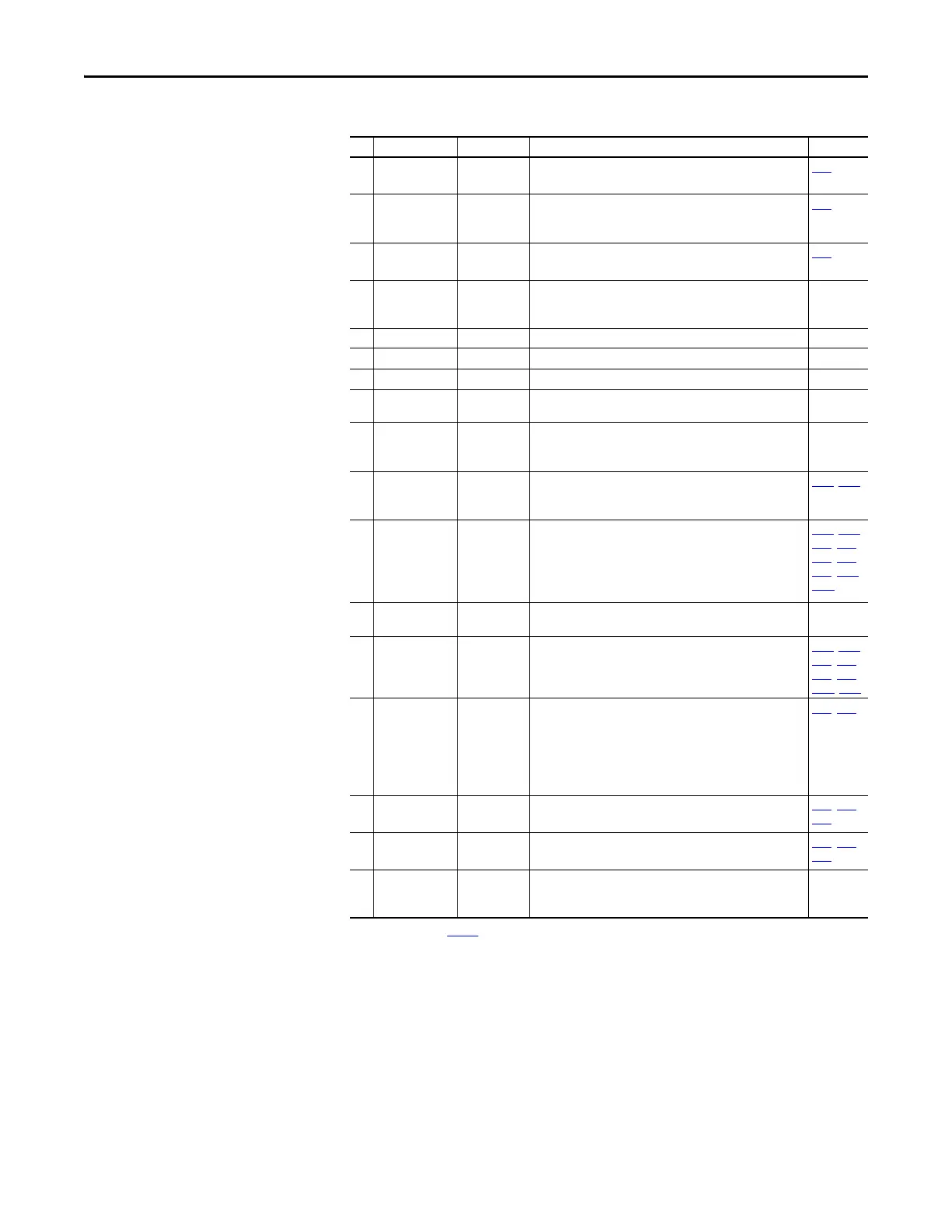
06 DigIn TermBlk 06 Preset Freq Program with t066 [DigIn TermBlk 06].
Current consumption is 6 mA.
t066
07 DigIn TermBlk 07/
Pulse In
Start Source 2
+ Speed
Reference2
Program with t067 [DigIn TermBlk 07]. Also functions as a Pulse
Train input for reference or speed feedback. The maximum
frequency is 100 kHz. Current consumption is 6 mA.
t067
08 DigIn TermBlk 08 Jog Forward Program with t068 [DigIn TermBlk 08].
Current consumption is 6 mA.
t068
C1 C1 – This terminal is tied to the RJ-45 port shield. Tie this terminal to
a clean ground in order to improve noise immunity when using
external communication peripherals.
–
C2 C2 – This is the signal common for the communication signals. –
S1 Safety 1 – Safety input 1. Current consumption is 6 mA. –
S2 Safety 2 – Safety input 2. Current consumption is 6 mA. –
S+ Safety +24V – +24V supply for safety circuit. Internally tied to the +24V DC
source (Pin 11).
–
11 +24V DC – Referenced to Digital Common.
Drive supplied power for digital inputs.
Maximum output current is 100 mA.
–
12 +10V DC – Referenced to Analog Common.
Drive supplied power for 0...10V external potentiometer.
Maximum output current is 15 mA.
P047
, P049
13 ±10V In Not Active For external 0-10V (unipolar) or ±10V (bipolar) input supply or
potentiometer wiper.
Input impedance:
Voltage source = 100 kΩ
Allowable potentiometer resistance range = 1...10 kΩ
P047, P049,
t062, t063,
t065, t066,
t093, A459,
A471
14 Analog Common – Return for the analog I/O. Electrically isolated (along with the
analog I/O) from the rest of the drive.
–
15 4-20mA In Not Active For external 4-20 mA input supply.
Input impedance = 250 Ω
P047
, P049,
t062, t063,
t065, t066,
A459, A471
16 Analog Output OutFreq 0-10 The default analog output is 0-10V. To convert a current value,
change the Analog Output jumper to 0-20 mA. Program with
t088 [Analog Out Sel]. Maximum analog value can be scaled
with t089 [Analog Out High].
Maximum Load: 4-20 mA = 525 Ω (10.5V)
0-10V = 1 kΩ (10 mA)
t088, t089
17 Opto Output 1 Motor Running Program with t069 [Opto Out1 Sel].
Each Opto-Output is rated 30V DC 50 mA (Non-inductive).
t069, t070,
t075
18 Opto Output 2 At Frequency Program with t072 [Opto Out1 Sel].
Each Opto-Output is rated 30V DC 50 mA (Non-inductive).
t072, t073,
t075
19 Opto Common – The emitters of the Optocoupler Outputs (1 and 2) are tied
together at Optocoupler Common. Electrically isolated from the
rest of the drive.
–
(1) See Footnote (1) on page 37.
Control I/O Terminal Designations
No. Signal Default Description Parameter

 Loading...


