2-76 Digital Inputs
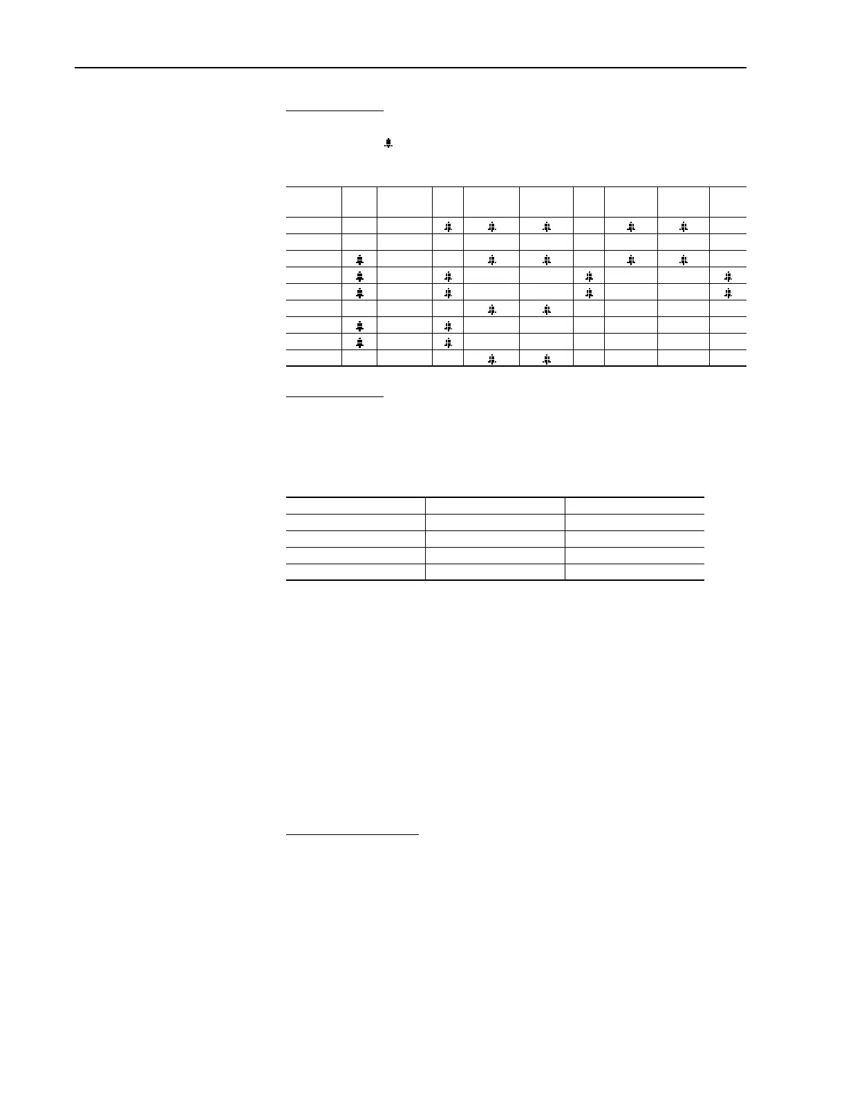
“DigIn CflctB” indicates a digital Start input has been configured without a
Stop input or other functions are in conflict. Combinations that conflict are
marked with a “ ” and will cause an alarm.
Table 2.K Input function combinations that produce “DigIn CflctB” alarm
“Digin CflctC” indicates that more than one physical input has been
configured to the same input function, and this kind of multiple
configuration isn’t allowed for that function. Multiple configuration is
allowed for some input functions and not allowed for others.
The input functions for which multiple configuration is not allowed are:
There is one additional alarm that is related to digital inputs: the “Bipolar
Cflct” alarm occurs when there is a conflict between determining motor
direction using digital inputs on the terminal block and determining it by the
polarity of an analog speed reference signal.
Note that the drive will assert an alarm when the user sets up a illegal
configuration rather than refusing the first parameter value that results in
such a configuration. This is necessary because the user may have to change
several parameters one at a time in order to get to a new desired
configuration, and some of the intermediate configurations may actually be
illegal. Using this scheme, the user or a network device can send parameter
updates in any order when setting up the digital input configuration.
The “Bipolar Cflct”
alarm occurs when there is a conflict between
determining motor direction using digital inputs on the terminal block and
determining it by some other means.
When [Direction Mode] is “Bipolar”, the drive uses the sign of the reference
to determine drive direction; when [Direction Mode] is “Reverse Dis”, then
the drive never permits the motor to run in the reverse direction. In both of
these cases, the terminal block inputs cannot be used to set direction, so this
alarm is asserted if any digital input function that can set motor direction is
configured.
Start Stop–CF Run Run Fwd Run Rev Jog Jog Fwd Jog Rev
Fwd/
Rev
Start
Stop–CF
Run
Run Fwd
Run Rev
Jog
Jog Fwd
Jog Rev
Fwd / Rev
Forward/Reverse Run Forward Stop Mode B
Speed Select 1 Run Reverse Bus Regulation Mode B
Speed Select 2 Jog Forward Accel2 & Decel2
Speed Select 3 Jog Reverse Accel 2
Run Decel 2

 Loading...


