2-6 Alarms
Drive Alarm word; that is, the same bits in both the Drive Alarm Word and
the Alarm Configuration Word represent the same alarm.
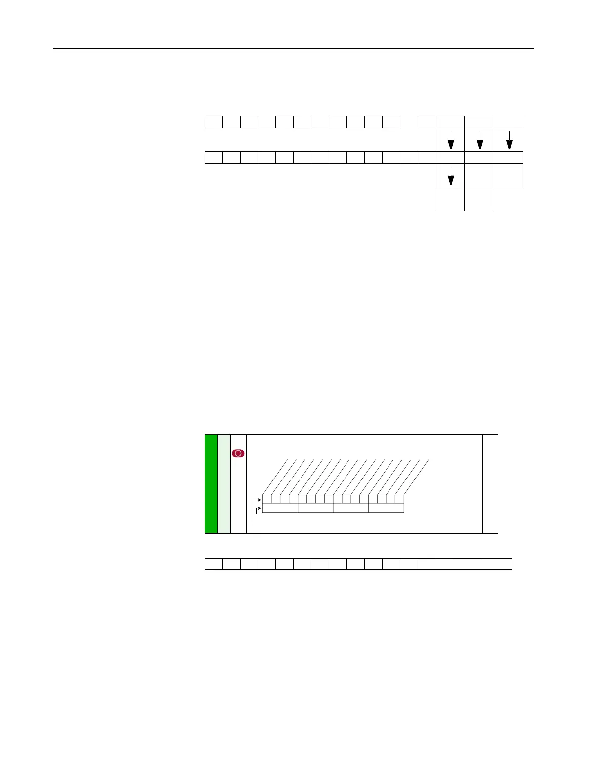
The configuration bits act as a mask to block or pass through the alarm
condition to the active condition. An active alarm will be indicated on the
LCD HIM and will cause the drive alarm status bit to go high (“1”) in the
Drive Status word (Bit 6, parameter 209). This bit can then be linked to a
digital output for external annunciation. As default, all configuration bits
are high (“1”). Note that setting a configuration bit to “0” to “mask” an
alarm does not affect the status bit in the Drive Alarm parameter, only its
ability to annunciate the condition.
Application
A process is being controlled by a PowerFlex drive. The speed reference to
the drive is a 4-20 mA analog signal from a sensor wired to Analog Input 1.
The input is configured for mA by setting the corresponding bit in [Anlg In
Config] to “1”
The input is scaled for 4-20 mA by setting [Analog In 1 Lo] to “4” mA and
[Analog In 1 Hi] to “20” mA.
Drive Alarm
111
Alarm Config
100
XX
Active
Alarm
Inactive
Alarm
Inactive
Alarm
320 [Anlg In Config]
Selects the mode for the analog inputs.
322
325
323
326
Analog In Config
01
0xx 0xxxxxxxxxxxx
10 01234567891112131415
1 = Current
0 = Voltage
x = Reserved
Bit #
Factory Default Bit Values
An1 0=V 1=mA
An2 0=V 1=mA
 Loading...


